Control method and control device for virtual synchronous generator

A technology of virtual synchronization and control method, which is applied in the field of microgrid, can solve the problems of system safety operation hazards and disturbances, and achieve the effect of quick response and reduced running time

Pending Publication Date: 2021-11-16
GUOCHUANG INNOVATION CENTER OF MOBILE ENERGY (JIANGSU) CO.,LTD.
View PDF0 Cites 1 Cited by
  • Summary
  • Abstract
  • Description
  • Claims
  • Application Information

AI Technical Summary

Problems solved by technology

In the related technology, when the inverter adopts the VSG control algorithm to simulate the output characteristics of the traditional synchronous generator, it uses a constant rotor inertia for control. Although it can ensure the stability of the system when the system disturbance occurs, but in the process of eliminating the disturbance In the middle, another disturbance may occur during the frequency response recovery period, which will bring greater harm to the safe operation of the system

Method used


Image

  • Control method and control device for virtual synchronous generator
  • Control method and control device for virtual synchronous generator
  • Control method and control device for virtual synchronous generator

Examples


Embodiment 1

[0075] Initially, the inverter outputs 20kW active power. At 0.15s, the system has a disturbance that increases the active power by 5kW. After 0.1s, the disturbance is eliminated, and the load returns to the rated state.

[0076] Figure 10 is the active power change process, Figure 11 It is a comparison chart of the frequency response curve under fixed rotor inertia control and the frequency response curve under adaptive control rotor inertia.

Embodiment 2

[0078] Initially, the inverter outputs 20kW active power. At 0.15s, the system has a disturbance that reduces the active power by 5kW. After 0.1s, the disturbance is eliminated, and the load returns to the rated state.

[0079] Figure 12 is the diagram of the active power change process, Figure 13 It is a comparison chart of the frequency response curve under fixed rotor inertia control and the frequency response curve under adaptive control rotor inertia.

[0080] By simulation results Figure 12 and Figure 13 It can be seen that the present invention can maintain a certain stability of the system in the event of system disturbance by adaptively controlling the rotor inertia, and can restore the frequency response to the normal operation state quickly and without impact when the disturbance is eliminated.

[0081] It has been verified that the control method of the virtual synchronous generator proposed by the present invention is effective.

[0082] In summary, accord...


PUM


Abstract

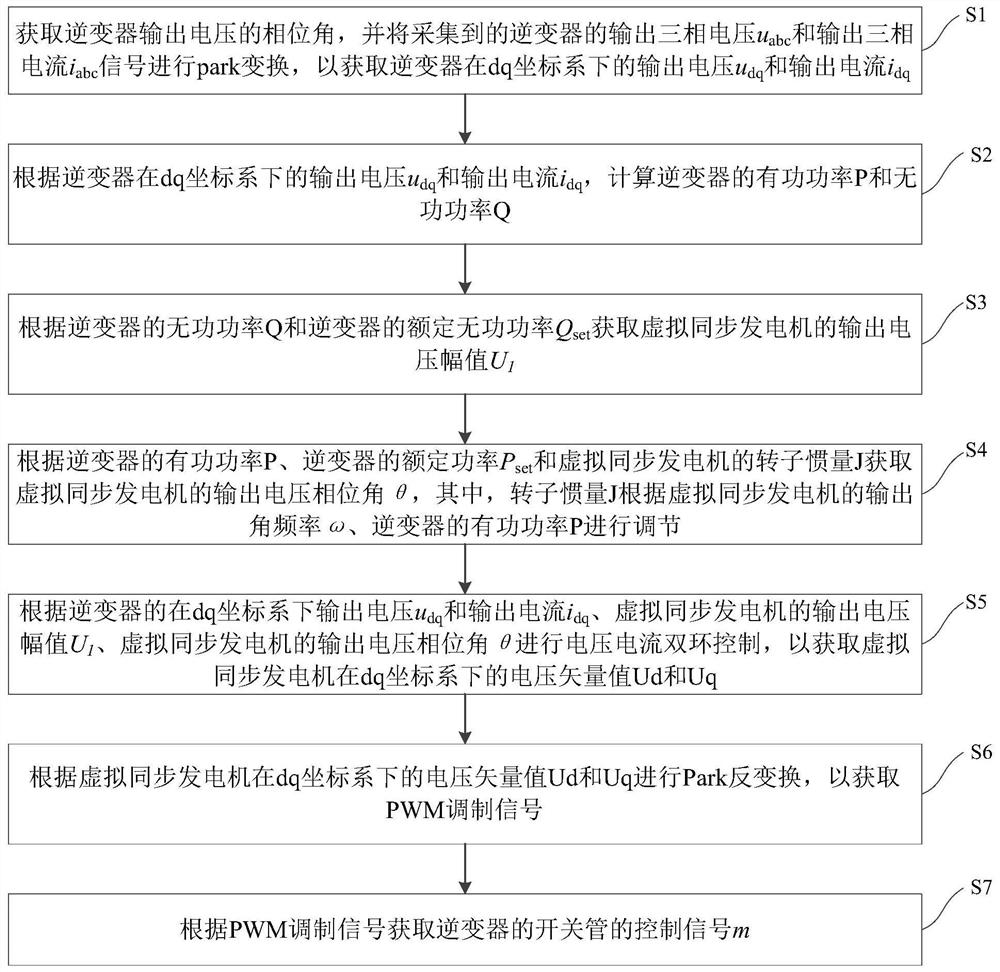
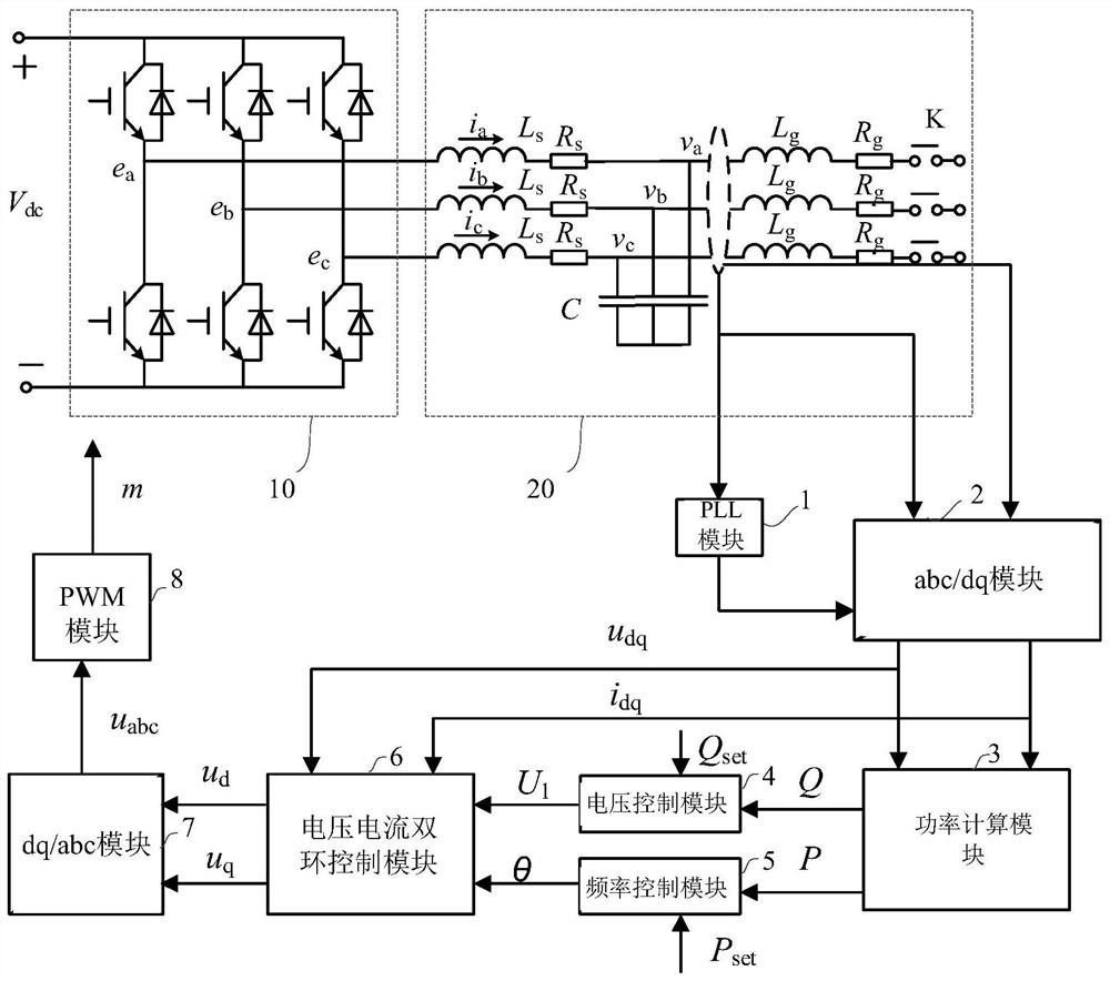
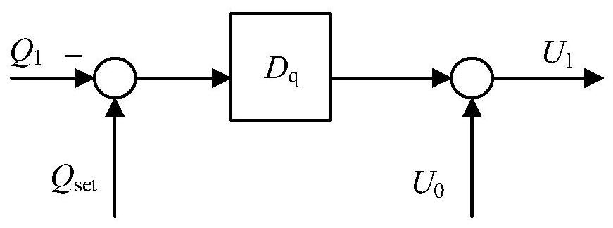
The invention provides a control method and control device for a virtual synchronous generator, and the method comprises the steps: obtaining an output voltage udq and an output current idq of an inverter under a dq coordinate system; calculating active power P and reactive power Q of the inverter according to udq and idq; obtaining an output voltage amplitude U1 according to the Q and the rated reactive power Qset; obtaining a virtual output voltage phase angle theta according to the P, rated power Pset and rotor inertia J, and adjusting J according to output angular frequencies omega and P; acquiring Ud and Uq according to udq, idq, U1 and theta; obtaining a PWM modulation signal according to the Ud and the Uq; and obtaining a control signal of a switching tube of the inverter according to the PWM modulation signal. According to the method, the inertia of the rotor is adaptively adjusted when the virtual synchronous generator is controlled, so that the inverter can maintain certain stability when the load is disturbed, and quick response can be realized when the disturbance is eliminated.

Description

technical field [0001] The invention relates to the technical field of microgrids, in particular to a control method for a virtual synchronous generator and a control device for a virtual synchronous generator. Background technique [0002] In recent years, microgrids have received more and more attention, in which distributed power sources need to achieve energy output through inverters. The traditional inverter algorithm only considers the quick response of the system and ignores the impact on the grid. Therefore, the virtual synchronous generator control strategy is adopted, so that the output of the inverter can simulate the output characteristics of the traditional synchronous generator, and a certain stability can be maintained when the disturbance occurs in the system. In the related technology, when the inverter adopts the VSG control algorithm to simulate the output characteristics of the traditional synchronous generator, it uses a constant rotor inertia for contr...

Claims


Application Information

Patent Timeline
Patent Type & Authority Applications(China)
IPC IPC(8): H02J3/38H02J3/40H02M7/5387H02M1/12H02P21/14H02P21/18H02P21/22
CPCH02J3/381H02J3/40H02M7/53871H02M1/126H02P21/14H02P21/18H02P21/22
Inventor 李国策刘博江伟石
Owner GUOCHUANG INNOVATION CENTER OF MOBILE ENERGY (JIANGSU) CO.,LTD.
Why Eureka
Try Eureka