Heat dissipation shaping device for cable processing

A sizing device and cable technology, applied in the direction of cable/conductor manufacturing, circuits, electrical components, etc., can solve the problems of unfavorable cable insulation layer formation and sizing, insulation layer is easy to shrink and wrinkle, heat dissipation and cooling effect is not good, and it is not easy to achieve Shrinkage and wrinkling, reducing the large disturbance of water flow, and avoiding the effect of water flow disturbance

Inactive Publication Date: 2020-11-24
匠桥智谷科技(涡阳)有限公司
View PDF0 Cites 0 Cited by
  • Summary
  • Abstract
  • Description
  • Claims
  • Application Information

AI Technical Summary

Problems solved by technology

Extrusion of the insulation layer is usually achieved by an extruder. The extruded cable needs to be cooled in a cooling water tank. The existing cooling water tank of the extruder usually has only one chamber. The temperature of the insulation layer just extruded from the extruder Higher, if the temperature difference between the higher temperature insulating layer and the cooling water is large, it is easy to damage the insulating layer, making the insulating layer easy to shrink and wrinkle, which is not conducive to the formation and shaping of the cable insulating layer; and when cooling the insulating layer, If the water flow disturbance is large during water cooling, it will also affect the formation of the insulating layer, which is not conducive to the formation and shaping of the cable insulation layer, but when the water flow disturbance is small, the heat dissipation and cooling effect is not good.

Method used

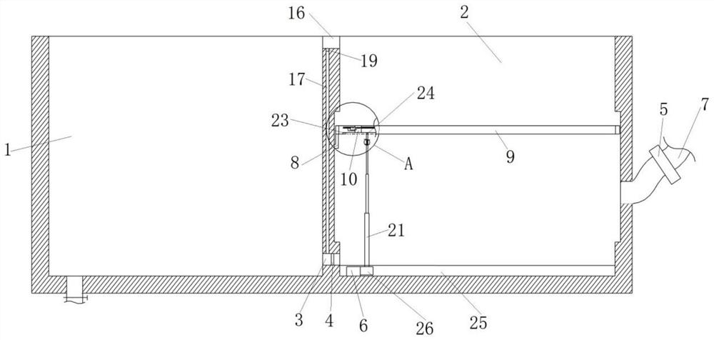
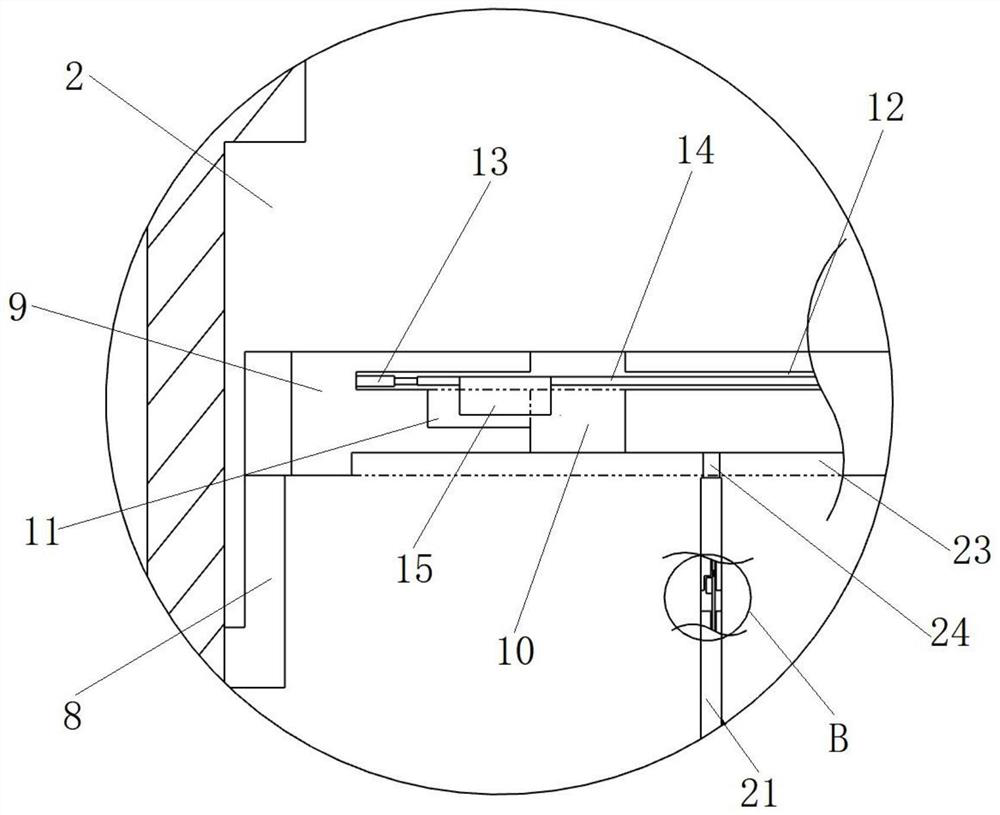
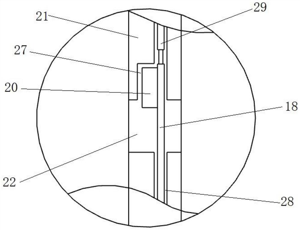

Image

  • Heat dissipation shaping device for cable processing
  • Heat dissipation shaping device for cable processing
  • Heat dissipation shaping device for cable processing

Examples


Embodiment Construction

[0021] In order to make the object, technical solution and advantages of the present invention clearer, the present invention will be described in further detail below in conjunction with specific embodiments and with reference to the accompanying drawings.

[0022] It should be noted that, unless otherwise defined, the technical terms or scientific terms used in the embodiments of the present invention shall have the usual meanings understood by those skilled in the art to which the present disclosure belongs. "First", "second" and similar words used in the present disclosure do not indicate any order, quantity or importance, but are only used to distinguish different components. "Comprising" or "comprising" and similar words mean that the elements or items appearing before the word include the elements or items listed after the word and their equivalents, without excluding other elements or items. Words such as "connected" or "connected" are not limited to physical or mechan...


PUM


Abstract

The invention discloses a heat dissipation shaping device for cable processing. The device comprises a first pool, one side of the first pool is connected with a second pool; a cavity is formed in theside wall of the second pool; a heating plate is arranged in the cavity; the first pool is communicated with the second pool through a circulating pipe; the second pool is communicated with a water delivery pipe; a second pump body is arranged in the water delivery pipe; an up-down moving plate is arranged in the second pool; the up-down moving plate is slidably connected with the inner side wallof the second pool; a rail groove is formed in the inner side wall of the second pool; a sliding block connected with the up-and-down moving plate is connected in the rail groove in a sliding manner;a plurality of first screen holes are formed in the up-down moving plate, a first lifting assembly is connected to the lower end of the up-down moving plate and used for controlling the up-down moving plate to move up and down, a multi-section telescopic plate is connected to the lower end face of the up-down moving plate, and the lower end of the multi-section telescopic plate is connected withthe lower end face in the second pool. According to the invention, heat dissipation and shaping of the cable just extruded from the plastic extruding machine are facilitated.

Description

technical field [0001] The invention relates to the technical field of cable processing equipment, in particular to a heat dissipation and shaping device for cable processing. Background technique [0002] The cable is an indispensable connecting cable in electrical equipment. It is generally composed of an inner conductive cable and multiple outer layers. The inner conductive cable is twisted from multiple single wires. The production process of the cable is continuous. It generally includes the following processes: drawing - twisting - extruding insulation layer - forming cable - extruding sheath layer - product testing and acceptance. Extrusion of the insulation layer is usually achieved by an extruder. The extruded cable needs to be cooled in a cooling water tank. The existing cooling water tank of the extruder usually has only one chamber. The temperature of the insulation layer just extruded from the extruder Higher, if the temperature difference between the higher te...

Claims


Application Information

Patent Timeline
Patent Type & Authority Applications(China)
IPC IPC(8): H01B13/30H01B13/00
CPCH01B13/00H01B13/30
Inventor 何仙章健
Owner 匠桥智谷科技(涡阳)有限公司
Why Eureka
Try Eureka