Fixing device, reaction cavity and plasma processing device

A fixing device and reaction chamber technology, applied in the field of plasma processing equipment, can solve the problems of damage to electronic devices, adverse effects of process environment, leakage of heat exchange medium, etc., so as to increase the processable area, avoid adverse effects, and reduce processing. effect of difficulty

Active Publication Date: 2015-08-19
BEIJING NAURA MICROELECTRONICS EQUIP CO LTD
View PDF8 Cites 16 Cited by
  • Summary
  • Abstract
  • Description
  • Claims
  • Application Information

AI Technical Summary

Problems solved by technology

[0005] However, this has the following problem again, that is, since there is a vertical gap between the upper surface of the workpiece 101 and the lower surface of the fixed ring plate 104 after the base 102 is lowered by a predetermined distance relative to the fixed ring plate 104 , which causes the heat exchange medium flowing into the gap between the lower surface of the processed workpiece 101 and the bearing surface of the base 102 to leak into the reaction chamber 100 through the vertical gap, causing damage to the process in the reaction chamber 100 The environment has adverse effects, so that when the base 102 drops a

Method used


Image

  • Fixing device, reaction cavity and plasma processing device
  • Fixing device, reaction cavity and plasma processing device
  • Fixing device, reaction cavity and plasma processing device

Examples


Embodiment Construction

[0038] In order to enable those skilled in the art to better understand the technical solution of the present invention, the fixing device, reaction chamber and plasma processing equipment provided by the present invention will be described in detail below with reference to the accompanying drawings.

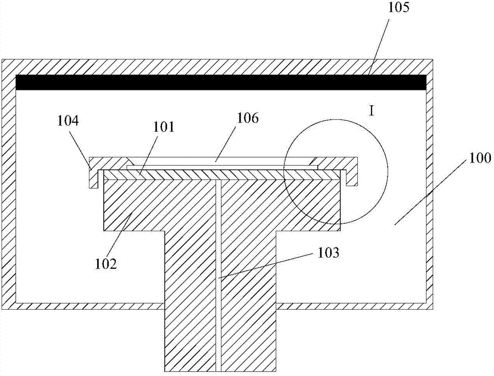
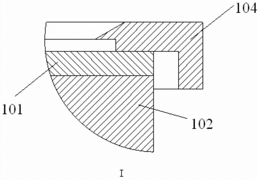
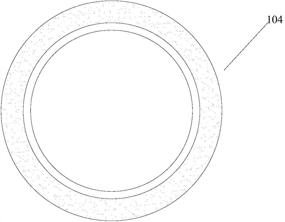
[0039] Figure 4A It is a sectional view of the fixing device provided by the first embodiment of the present invention. Figure 4B for Figure 4A Top view of the fixture. Please also refer to Figure 4A and Figure 4B , the fixing device is used to fix the workpiece 201 to be processed on the bearing surface of the base 202 located in the reaction chamber, the fixing device includes a fixing ring plate 203 above the base 202, and the material used for the fixing ring plate 203 includes stainless steel Equal high-density materials, on the inner peripheral wall of the fixed ring plate 203 (that is, the inner peripheral wall of the annular hole 204 of the fixed ring plate 203)...


PUM


Abstract

The invention provides a fixing device, a reaction cavity and a plasma processing device; the fixing device is used for fixing a processed workpiece on a bearing surface of a pedestal in the reaction cavity, and comprises a fixing annular plate positioned above the pedestal; an inner periphery wall of the fixing annular plate is provided with a plurality of fixing paws arranged on the periphery at intervals; the bottom surface of each fixing paw is stacked on an edge portion of the top surface of the processed workpiece on the bearing surface of the pedestal, thus fixing the processed workpiece on the bearing surface of the pedestal. The pedestal needs not to be lowered relative to the fixing device, and the processing area of the processed workpiece can be enlarged, thus satisfying later procedure needs and reducing processing difficulty of the later procedure, and ensuring technical stability.

Description

technical field [0001] The invention belongs to the technical field of microelectronic processing, and in particular relates to a fixing device, a reaction chamber and plasma processing equipment. Background technique [0002] Through Silicon Via (TSV for short) technology is currently the key technology to realize the miniaturization of electronic product packaging. In the subsequent packaging process, TSVPVD equipment is mainly used to deposit thin films in the TSV process, and because the processed workpieces for subsequent packaging processes are relatively thin, it is usually required to use a fixture to fix the processed workpieces on the carrier when depositing thin films. Machined on the upper surface of the base of the workpiece. [0003] figure 1 It is a cross-sectional view of the existing TSV PVD equipment. figure 2 for figure 1 Partial enlarged view of the middle I region. image 3 for figure 1 Top view of the fixture. Please also refer to figure 1 , ...

Claims


Application Information

Patent Timeline
IPC IPC(8): H01L21/687H01L21/67H01J37/32C23C14/34C23C14/50
CPCC23C14/34C23C14/50H01J37/32715H01J2237/3325H01L21/67011H01L21/68728
Inventor 郑金果
Owner BEIJING NAURA MICROELECTRONICS EQUIP CO LTD
Why Eureka
Try Eureka