Stator punching sheet of combination structure

A stator punching and combined structure technology, applied in the magnetic circuit shape/pattern/structure, magnetic circuit static components, etc., can solve the problems of time-consuming, laborious, narrow, and high material cost in embedding work, and reduce end leakage reactance. , the effect of simplifying the process and reducing the cost

Inactive Publication Date: 2015-08-19
HUZHOU CHARI MACHINERY & ELETRICAL SCI
View PDF11 Cites 0 Cited by
  • Summary
  • Abstract
  • Description
  • Claims
  • Application Information

AI Technical Summary

Problems solved by technology

However, there is a problem in the existing stator punches of similar structure. The open slot of the stator punch is in the inner ring, and the notch of the open slot is relatively narrow in a contracted state, which is very unfavorable to the coil winding. The existing stator coils are all After the strands are wound into a U shape, they are inserted into the punching groove by dislocation and superposition. The embedding work is time-consuming and laborious during assembly, and the material cost of the superposition and embedding method is high and the assembly is cumbersome.

Method used


Image

  • Stator punching sheet of combination structure
  • Stator punching sheet of combination structure
  • Stator punching sheet of combination structure

Examples


Embodiment 1

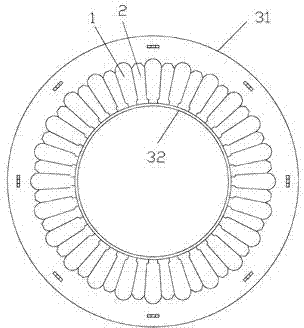
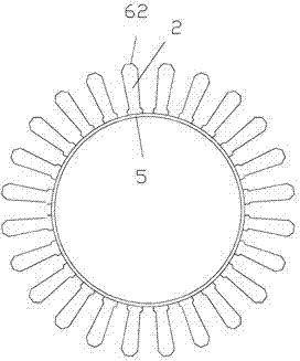
[0024] Such as figure 1 In the shown embodiment 1, a stator punching sheet with a combined structure has a hollow inner circular hole in the middle of the stator punching sheet, and 24 radially distributed holes are arranged between the outer edge of the stator punching sheet and the inner circular hole. Punching slots 1, between adjacent punching slots 1 on the stator punching sheet are 24 punching columns 2 for coil winding. punching tank such as Figure 4 As shown, a groove top 71 , a groove body 72 , a groove shoulder 73 and a groove 74 are included. The stator stamping is divided into a first stamping part 31 and a second stamping part 32 at the end of the stamping column 2 .

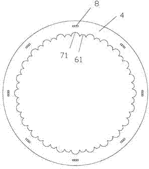
[0025] The first punching unit 31 such as figure 2 As shown, including the outer ring body 4, the inner ring portion of the outer ring body is provided with an annular array of concave sides 61 for separating and forming, and arc-shaped sides are arranged between adjacent concave-shaped sides 6...

Embodiment 2

[0031] The difference from Embodiment 1 is that the concave side and the convex side used for separation are arc-shaped locking structures.


PUM


Abstract

The invention discloses a stator punching sheet of a combination structure. The central portion of the stator punching sheet is provided with a hollow inner circular hole, a plurality of radially distributed punching sheet grooves are arranged between the outer edge of the stator punching sheet and the inner circular hole, punching sheet columns for winding coils are arranged between adjacent punching sheet grooves on the stator punch sheet, the stator punching sheet is divided into a first punching sheet portion and a second punching sheet portion at the end portions of the punching sheet columns, the first punching sheet portion comprises an outer ring body, and the second punching sheet portion comprises the punching sheet columns and a connecting ring. The stator punching sheet provided by the invention is divided into two portions, the winding mode of the coils is changed, the cost is decreased, the process is simplified, and the end portion leakage reactance is reduced.

Description

technical field [0001] The invention relates to a stator punch on an electric motor, in particular to a stator punch with a composite structure. Background technique [0002] Most of the stamping sheets of the stator on the existing electric motor are integral structures, and are provided with an annular ring of punching grooves, and the punching grooves are opened on the annular inner ring. For example, Chinese Patent Publication No.: CN202931048U, in the patent document published on May 8, 2013, discloses a stator punching sheet of a washing machine motor. The middle part of the stator punching sheet is made with a hollow inner circular hole, and the outer circumference of the stator punching sheet is There are several stamping slots evenly distributed along the radial direction of the stator stamping between the edge and the hollow inner hole, which is not only low in cost, but also has the most optimized temperature rise of the motor and less noise in use. It is also sui...

Claims


Application Information

Patent Timeline
Patent Type & Authority Applications(China)
IPC IPC(8): H02K1/16
Inventor 沈利忠
Owner HUZHOU CHARI MACHINERY & ELETRICAL SCI
Why Eureka
Try Eureka