A Bearingless Half-tooth Wound Switched Reluctance Motor

A switched reluctance motor and bearingless technology, which is applied in the direction of motors, electric vehicles, electrical components, etc., can solve the limitations of the bearingless switched reluctance motor's actual load capacity, low fault tolerance and reliability, and serious magnetic circuit coupling. problem, to achieve the effect of low winding difficulty, good heat dissipation, and small moment of inertia

Active Publication Date: 2015-11-18
SOUTHEAST UNIV
View PDF3 Cites 0 Cited by
  • Summary
  • Abstract
  • Description
  • Claims
  • Application Information

AI Technical Summary

Problems solved by technology

[0006] At present, the proposed bearingless switched reluctance motor mainly winds two sets of windings on each stator tooth of the motor, which respectively undertake the functions of torque winding and suspension force winding. In this way, the number of coils of the motor is twice the number of stator teeth. times, the bearingless switched reluctance motor using this method has a complex structure, low slot fill rate, and the torque winding and the suspension force winding are nested on the same stator tooth, the magnetic circuit is almost identical, and the fault tolerance and reliability Low, the magnetic circuit coupling is very serious, which limits the actual load capacity of the bearingless switched reluctance motor and becomes a major bottleneck in its engineering application

Method used


Image

  • A Bearingless Half-tooth Wound Switched Reluctance Motor
  • A Bearingless Half-tooth Wound Switched Reluctance Motor
  • A Bearingless Half-tooth Wound Switched Reluctance Motor

Examples


Embodiment 1

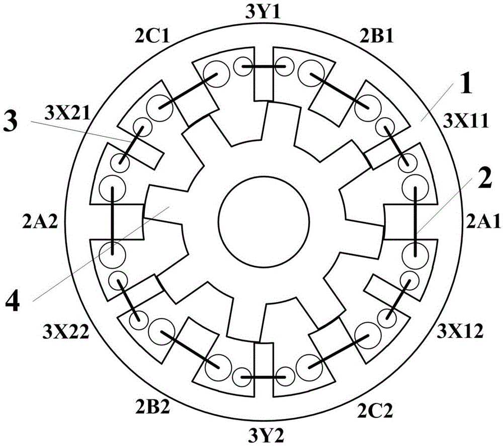
[0032] Embodiment 1: Take the structure of a three-phase stator with 12 slots / rotor with 8 poles switched reluctance motor as an example for illustration.

[0033] like figure 1 As shown, this embodiment adopts a three-phase stator with 12 slots / rotor with an 8-pole motor structure. There are 12 salient pole teeth on the stator, and a concentrated winding coil is set on each stator tooth. There are 12 coils in total. The clockwise direction is called: the first torque winding coil 2A1, the first suspension force winding coil 3X11, the second torque winding coil 2B1, the second suspension force winding coil 3Y1, the third torque winding coil 2C1, and the third suspension force coil Winding coil 3X21, fourth torque winding coil 2A2, fourth suspension force winding coil 3X22, fifth torque winding coil 2B2, fifth suspension force winding coil 3Y2, sixth torque winding coil 2C2 and sixth suspension force winding coil 3X12.

[0034]The torque winding 2 includes a first torque wind...

Embodiment 2

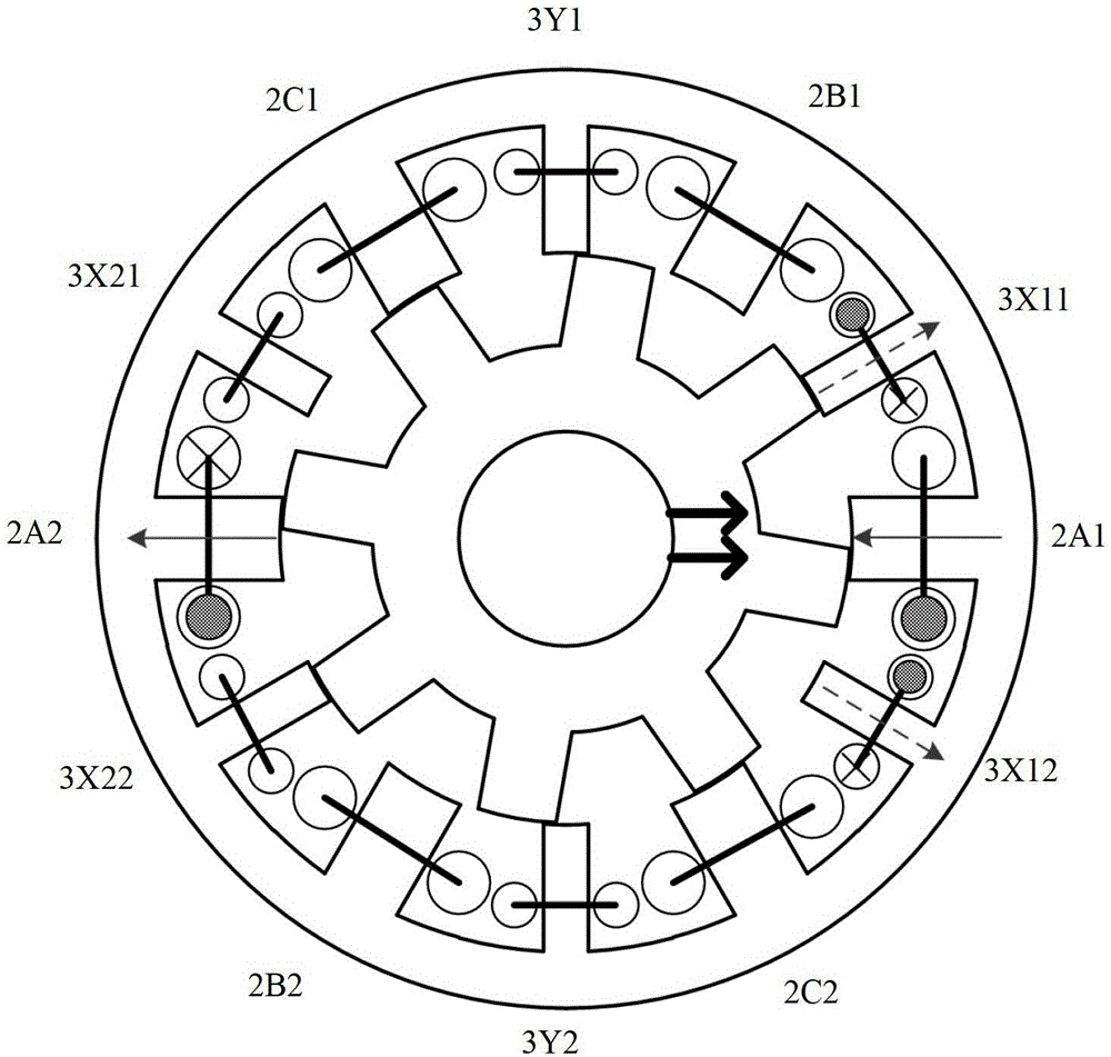
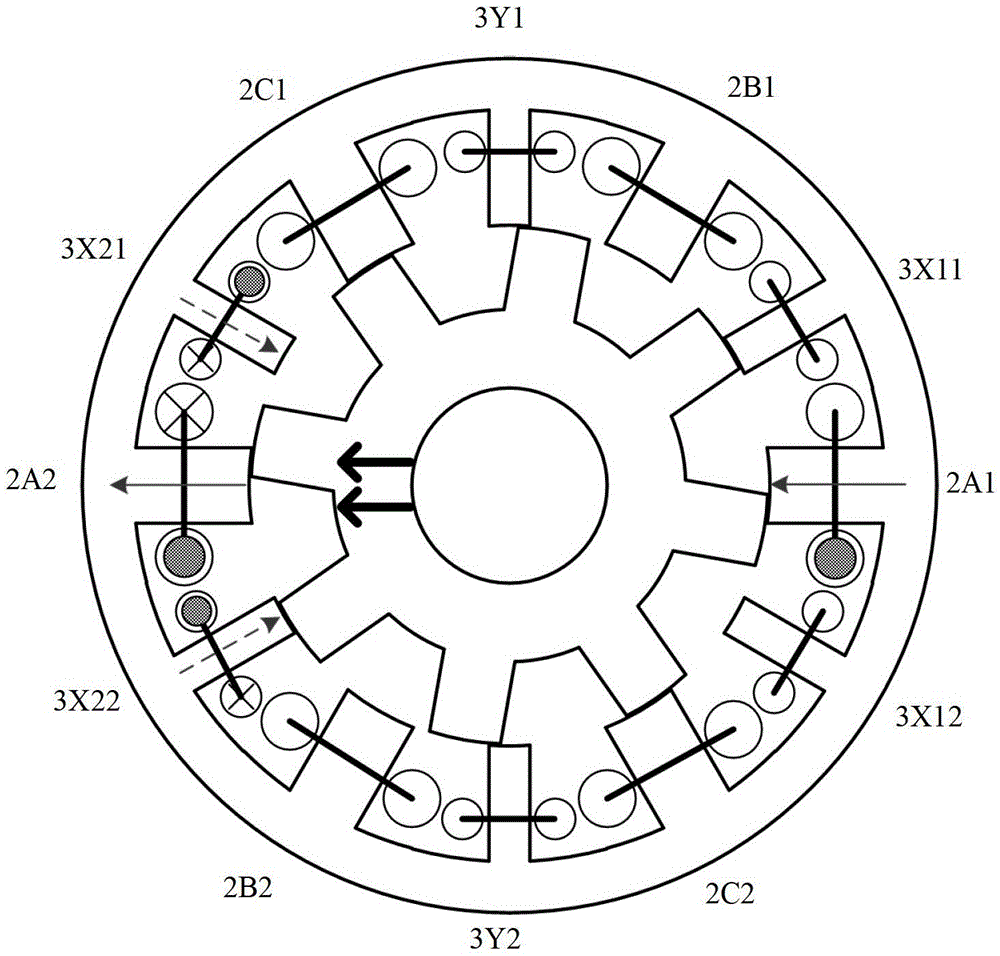
[0038] Embodiment 2: The structure of a four-phase stator with 8 slots / rotor with 6 poles switched reluctance motor is used as an example for illustration.

[0039] Such as image 3 As shown, this embodiment adopts a four-phase stator with 8 slots / rotor with 6 poles motor structure. There are 8 salient pole teeth on the stator, and a concentrated winding coil is set on each stator tooth. There are 8 coils in total. The clockwise direction is called: the first suspension force winding coil 3X11, the first torque winding coil 2A1, the second suspension force winding coil 3Y1, the second torque winding coil 2B1, the fourth suspension force winding coil 3X22, the fourth torque winding coil Winding coil 2A2, fifth suspension force winding coil 3Y2, and fifth torque winding coil 2B2.

[0040] The torque winding 2 comprises a first torque winding coil 2A1, a second torque winding coil 2B1, a fourth torque winding coil 2A2 and a fifth torque winding coil 2B2, the first torque winding...


PUM


Abstract

The invention discloses a bearingless half-tooth-winding switched reluctance motor. An even number of stator teeth are arranged on a stator. A centralized short-chord winding coil is sleeved on each stator teeth and comprises a torque winding and a suspension force winding which are arranged at an interval. The torque windings are used for outputting mechanical torque, and the suspension force windings are used for controlling displacement of a motor rotor in a horizontal X-axis direction and a vertical Y-axis direction. The motor keeps the advantage of simple and firm structure of a switched reluctance machine, only one coil is arranged on each stator tooth, groove full rate is high, and reliability is good; meanwhile bearingless running of the switched reluctance motor is realized by ingenious change of winding modes, so that the switched reluctance motor can give full play to the advantage of being suitable for high-speed and ultra-high-speed working, and has high theoretical and practical value.

Description

technical field [0001] The invention relates to the technical field of motor manufacturing, in particular to a novel bearingless switched reluctance motor with half-tooth windings. Background technique [0002] With the rapid rise in price and unstable supply of rare earth permanent magnet materials, switched reluctance motor systems without permanent magnets have attracted more and more attention. The switched reluctance motor has a double-salient pole structure. The stator and rotor are made of ordinary silicon steel sheets laminated. There is no permanent magnet or winding on the rotor. There are only concentrated windings on the stator. It works according to the principle of "minimum reluctance". The switched reluctance motor has low manufacturing and maintenance costs, simple and reliable structure, good robustness, small starting current, large torque, wide speed range, fast dynamic response, excellent fault tolerance and reliability. In addition, due to its rotor The...

Claims


Application Information

Patent Timeline
Patent Type & Authority Patents(China)
IPC IPC(8): H02K3/28H02K1/16H02N15/00
CPCY02T10/641Y02T10/64
Inventor 花为华浩鹿泉峰程明
Owner SOUTHEAST UNIV
Why Eureka
Try Eureka