
Differential output digital buffer and control method thereof

A digital buffer, differential output technology, applied in the direction of logic circuit connection/interface layout, etc., can solve the problems of high power consumption and parasitic capacitance consumes more energy, and achieve the effect of reducing power consumption and efficient transmission

Active Publication Date: 2015-08-19
SILICON STAR TECH
View PDF6 Cites 1 Cited by
  • Summary
  • Abstract
  • Description
  • Claims
  • Application Information

AI Technical Summary

Problems solved by technology

[0003] The purpose of the present invention is to overcome the technical problems that the parasitic capacitance in the existing differential output digital buffer consumes more energy and consumes more power, and provides a differential output digital buffer capable of reducing power consumption and its control method

Method used


Image

  • Differential output digital buffer and control method thereof
  • Differential output digital buffer and control method thereof

Examples


Embodiment

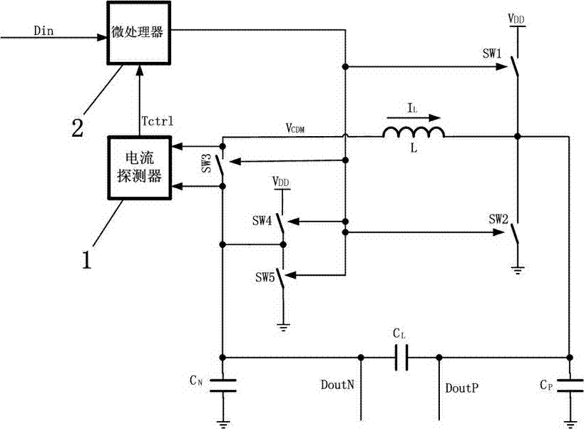
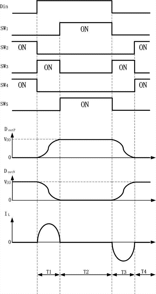
[0026] Embodiment: a kind of differential output digital buffer of this embodiment, such as figure 1 As shown, it includes a controller, an inductor L, a capacitor CL, a capacitor CN, a capacitor CP, a switch SW1, a switch SW2, a switch SW3, a switch SW4 and a switch SW5, and the controller includes a current detector 1 and a microprocessor 2. The first conducting end of the switching tube SW3 is electrically connected to the first conducting end of the switching tube SW4, the first conducting end of the switching tube SW5, one end of the capacitor CN and the first end of the capacitor CL, and the other end of the capacitor CN is grounded , the second conduction end of the switch tube SW3 is electrically connected to one end of the inductor L, and the other end of the inductor L is connected to the first conduction end of the switch tube SW1, the first conduction end of the switch tube SW2, the first end of the capacitor CP, and the first end of the capacitor CL. The two ends ...


PUM


Abstract

The invention discloses a differential output digital buffer and a control method thereof. The differential output digital buffer includes a controller, an inductor L, a capacitor CL, a switch tube SW1, a switch tube SW2, a switch tube SW3, a switch tube SW4 and a switch tube SW5. The controller is used for detecting current flowing through the inductor L and controlling the switching-on and switching-off of the switch tube SW1, the switch tube SW2, the switch tube SW3, the switch tube SW4 and the switch tube SW5. The first end and the second end of the capacitor CL are two output terminals of the differential output digital buffer. According to the invention, by utilizing LC oscillation, differential signals are driven in a lossless way, so that power consumption of the differential output digital buffer is reduced and an aim of efficiently transmitting wired differential voltage signals is achieved.

Description

technical field [0001] The invention relates to the technical field of digital buffers, in particular to a differential output digital buffer and a control method thereof. Background technique [0002] In some wired data transmission occasions, in order to suppress common-mode interference signals, differential lines are used to transmit fully differential voltage signals, and there will be parasitic capacitance between differential lines, and driving this parasitic capacitance will consume energy. The requirements are getting higher and higher, and this part of the consumed electric energy needs to be considered for recovery. Contents of the invention [0003] The purpose of the present invention is to overcome the technical problems that the parasitic capacitance in the existing differential output digital buffer consumes more energy and consumes more power, and provides a differential output digital buffer capable of reducing power consumption and a control method there...

Claims


Application Information

Patent Timeline
IPC IPC(8): H03K19/0175
CPCH03K19/0175
Inventor 陈锋
Owner SILICON STAR TECH
Learn More