
Optical element

An optical element, optical alignment technology, applied in the direction of optical elements, optics, polarizing elements, etc., can solve the problems of uneven optical characteristics, complex power supply system structure, difficult to achieve visual sensitivity and other problems

Active Publication Date: 2015-08-19
LG CHEM LTD
View PDF5 Cites 7 Cited by
  • Summary
  • Abstract
  • Description
  • Claims
  • Application Information

AI Technical Summary

Problems solved by technology

However, the above-mentioned method has the problem that since an additional external power supply must be provided to drive the smart diaphragm, the structure of the power supply system is complicated.
In this case, the retardation film has a problem in that a slight deviation of the optical axis on the side surface of the smart stop causes non-uniformity in optical characteristics, so that on the side surface of the smart stop Difficulty achieving uniform visual acuity

Method used

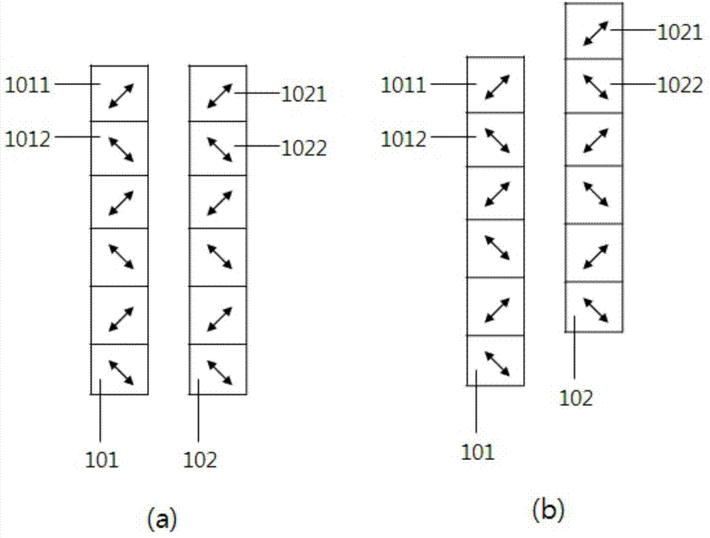
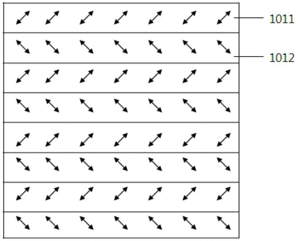
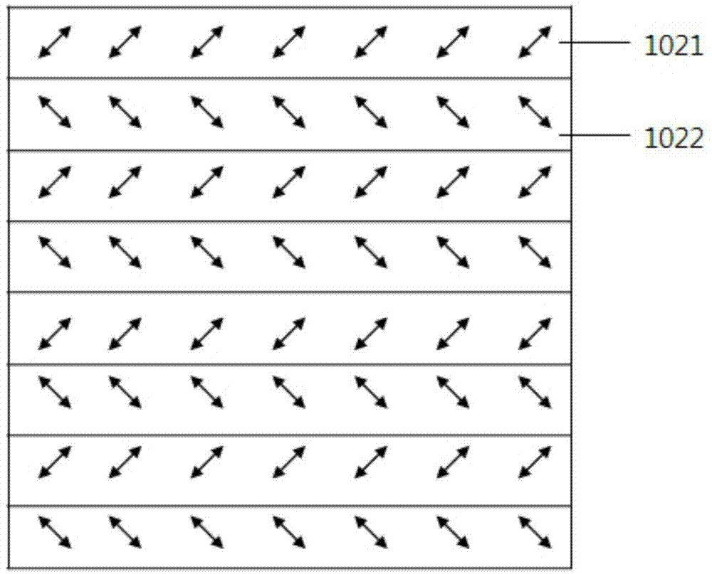

Image

  • Optical element
  • Optical element
  • Optical element

Examples


Embodiment 1

[0073] After drying, the thickness of the composition reaches about A composition for forming an optical alignment film was coated on one surface of the glass by means of a method, followed by drying in an oven at 80° C. for 2 minutes. The composition prepared by dissolving 5-norbornene-2-methylcinnamate (purchased from LG Chem Ltd.) in toluene solvent so that the concentration of the solids becomes 2 wt % was used as above for forming optical The composition of the alignment film.

[0074] Next, according to the method disclosed in Korean Patent Application No. 2010-0009723, the dried composition for forming an optical alignment film is aligned to form an optical alignment film comprising a first alignment region and a second alignment region aligned in different directions. Alignment film. Specifically, a pattern mask in which light-transmitting portions and light-blocking portions in a stripe shape (having a width of about 450 μm) were alternately formed in the vertical ...


PUM

PropertyMeasurementUnit
Absorbanceaaaaaaaaaa

Abstract

An optical element and a use of the optical element are provided. The exemplary optical element can be useful in realizing a smart blind having excellent transmission and blocking characteristics in front and lateral surfaces thereof without using a retardation film by employing a polarizing layer whose polarization characteristics are patterned using a guest / host-type dye layer including a polymerizable liquid crystal compound and a dichroic dye. Such an optical element may be applied to various light modulating devices such as smart blinds, smart windows, window protective films, flexible display elements, active retarders for displaying a 3D image, or viewing angle adjustment films.

Description

technical field [0001] The present application relates to an optical element and an intelligent diaphragm. Background technique [0002] Generally speaking, a smart diaphragm is a diaphragm capable of adjusting the light transmittance of sunlight, which involves smart windows, electronic curtains, transmission variable glass or photochromic glass. [0003] For example, the smart diaphragm may be composed of a light transmittance adjustment layer capable of adjusting light transmittance, and a driving circuit configured to apply a signal to the light transmittance adjustment layer to control the light transmittance adjustment layer. The smart diaphragm thus set can allow light to pass through or not pass through the entire glass according to the state of the applied voltage, and can also change the shading by controlling the transmittance. However, the above-mentioned method has a problem that an additional external power supply must be provided to drive the smart aperture, ...

Claims


Application Information

Patent Timeline
IPC IPC(8): G02B5/30G02B30/25
CPCG02B5/3016G02B27/26G02B30/25E06B9/24G02B5/30
Inventor 金信英李知妍朴文洙尹赫
Owner LG CHEM LTD
Learn More