Servo control system and control method for numerically controlled drilling machine tool

A servo control system and machine tool technology, applied in thread trimmers, manufacturing tools, metal processing mechanical parts, etc., can solve the problems of low production efficiency, waste of manual tap removal, and increased tapping torque, etc., to achieve convenient centralized control, improve Convenience and improved safety

Inactive Publication Date: 2015-08-26
汤林
View PDF8 Cites 5 Cited by
  • Summary
  • Abstract
  • Description
  • Claims
  • Application Information

AI Technical Summary

Problems solved by technology

During the tapping process, due to the aging of the drill bit, the tapping torque becomes larger, often causing the tap to break in the tapping hole, resulting in the problem of defective products, and waste of manual removal of the broken tap, resulting in low production efficiency

Method used


Image

  • Servo control system and control method for numerically controlled drilling machine tool
  • Servo control system and control method for numerically controlled drilling machine tool

Examples


Embodiment 1

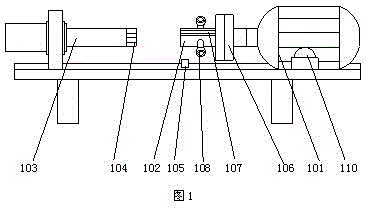
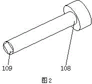
[0025] Such as figure 1 , 2 As shown, a servo control system for a numerically controlled drilling machine tool includes a servo motor 101 and a workpiece fixture 102 arranged on the servo motor 101. The servo motor 101 is respectively provided with a start button and a stop button, and the servo motor 101 passes The line is electrically connected to the control panel, and a hydraulic cylinder 103 is arranged on the opposite side of the servo motor 101. The axis of the hydraulic cylinder 103 is on the same straight line as the axis of the workpiece fixture 102. The opposite end is provided with a tap fixture 104, and a proximity switch 105 is arranged below the tap fixture 104. The proximity switch 105 is electrically connected to the control panel, and the rotational speed sensor is connected to the control panel through a line. A torque sensor is arranged on the top, and the torque sensor is connected to the control panel through a line. A cylinder 110 is arranged on one si...

Embodiment 2

[0032] The present invention also discloses a control method of a CNC drilling machine tool servo control system, including the following steps:

[0033] S1: Install the workpiece to be processed, and start the tap for tapping: monitor the workpiece speed in real time through the speed sensor, and send the speed information to the control panel for display, use the torque sensor to detect the torque of the workpiece fixture, and send the torque information to control panel;

[0034] S2: The control panel compares the received torque and speed information with the preset information, and sends control information to the servo motor to adjust the speed of the servo motor when the speed and torque exceed the preset range;

[0035] S3: The servo motor receives the information sent by the control panel, and adjusts the speed according to the information sent by the control panel. The torque sensor and the speed sensor detect the adjusted speed of the servo motor and the torque of t...


PUM


Abstract

The invention discloses a servo control system for a numerically controlled drilling machine tool. The servo control system comprises a servo motor and a workpiece clamp arranged on the servo motor. A starting button and a stop button are arranged on the servo motor, the servo motor is electrically connected with a control panel through a circuit, and a proximity switch is electrically connected with the control panel. A rotating speed sensor is arranged on the workpiece clamp and connected with the control panel through a circuit. A hydraulic cylinder is connected with the control panel through a circuit. The workpiece clamp is provided with a torque sensor which is connected with the control panel through a circuit. A cylinder is arranged on one side of the servo motor, and a telescopic rod of the cylinder is connected with a base of the servo motor. The rotating speed and the torque of a workpiece are detected in real time, are controlled within a reasonable range and can be adjusted in time according to needs, and use is prevented from being affected by breakage of a screw tap; the proximity switch is used for detecting the feed amplitude which is displayed through the control panel, so that feed is controlled, and machining precision is improved.

Description

technical field [0001] The invention relates to a CNC drilling machine tool servo control system and a control method thereof. Background technique [0002] At present, domestic CNC drilling machine tools have no torque protection function, and imported Spanish equipment has servo torque control and protection functions. During the tapping process, due to the aging of the drill bit, the tapping torque increases, often causing the tap to break in the tapping hole, resulting in the problem of defective products, and waste of manual removal of the broken tap, resulting in low production efficiency. Contents of the invention [0003] The purpose of the present invention is to provide a CNC drilling machine tool servo system and its control method that can be easily operated, which can improve the problems existing in the prior art, and control it within a reasonable range by detecting the rotational speed and torque of the workpiece in real time. At the same time, It can be a...

Claims


Application Information

Patent Timeline
Patent Type & Authority Applications(China)
IPC IPC(8): B23Q5/10B23Q5/26B23G1/18
CPCB23Q5/10B23G1/18B23Q5/26
Inventor 汤林
Owner 汤林
Why Eureka
Try Eureka