Suspension frame and maglev train with frame type traction linear motor in the middle

A technology of linear motor and suspension frame, which is applied in the direction of electric traction, electric vehicles, vehicle components, etc., can solve the problems of rhombus change and failure to maintain rectangle, etc., and achieve the effects of small fluctuation, enhanced passage, and convenient installation and maintenance

Active Publication Date: 2017-04-12
NAT UNIV OF DEFENSE TECH
View PDF8 Cites 0 Cited by
  • Summary
  • Abstract
  • Description
  • Claims
  • Application Information

AI Technical Summary

Problems solved by technology

This is because the suspension frame in the middle of the traction linear motor 1 transmits the thrust of the motor to the left and right suspension modules 2 through the main arm 4, and the main arm 4 is fixed to the traction linear motor 1. This force transmission method will cause the traction linear motor 1 to suffer Influenced by the front and rear positions of the left and right suspension modules 2, the parallelogram formed by the left and right suspension modules 2 and the anti-roll decoupling mechanism changes rhombically and cannot maintain a rectangle when cornering, so that the direction of the motor is basically parallel to the car body 6 instead of follow the track
The simulation data shows that the yaw angle between the motor and the track even reaches 6.5°, which will have an adverse effect on the thrust control of the motor when cornering

Method used


Image

  • Suspension frame and maglev train with frame type traction linear motor in the middle
  • Suspension frame and maglev train with frame type traction linear motor in the middle
  • Suspension frame and maglev train with frame type traction linear motor in the middle

Examples


Embodiment Construction

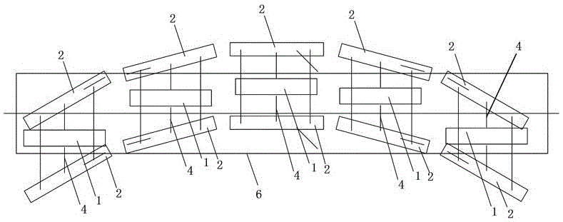
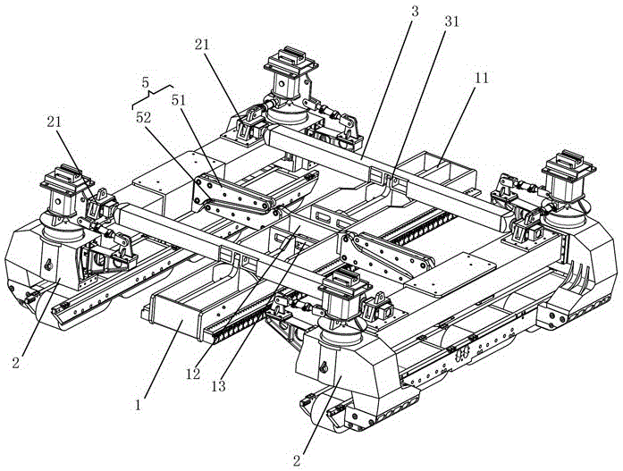
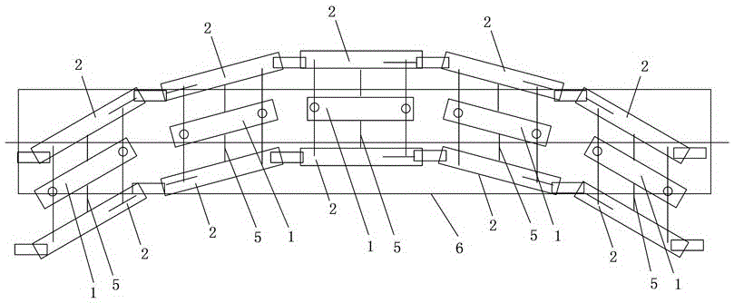
[0023] figure 2 It shows a suspension frame embodiment of a frame-type traction linear motor in the middle of the present invention, the suspension frame includes a traction linear motor 1, a pair of suspension modules 2 and a pair of beams 3, and the traction linear motor 1 is arranged in parallel on a pair of Between the suspension modules 2, a pair of crossbeams 3 are arranged at both ends of the suspension module 2, and each crossbeam 3 is connected between a pair of suspension modules 2, and the traction linear motor 1 is connected to the pair of crossbeams 3 through ball joint bearings. Both sides of the linear motor 1 are provided with at least one set of anti-roll decoupling mechanisms 5 , one end of the anti-roll decoupling mechanism 5 is hinged to the traction linear motor 1 , and the other end is hinged to the suspension module 2 . In the suspension frame of the frame-type traction linear motor of the present invention, the traction linear motor 1 and the beam 3 ar...


PUM


Abstract

The invention discloses a framed traction linear motor-centered suspension frame and a maglev train. The suspension frame comprises a traction linear motor, a pair of suspension modules and a pair of cross beams, wherein the traction linear motor is arranged between the pair of suspension modules in parallel; the pair of cross beams is arranged at the two ends of the suspension modules; each cross beam is connected between the pair of suspension modules; the traction linear motor is connected to the pair of cross beams through spherical hinge bearings; at least one set of anti-rolling decoupling mechanisms is respectively arranged at the two sides of the traction linear motor; and one ends of the anti-rolling decoupling mechanisms are hinged to the traction linear motor, and the other ends are hinged to the suspension modules. The maglev train comprises multiple train bodies and multiple framed traction linear motor-centered suspension frames; and the train bodies are mounted on the suspension frames. The framed traction linear motor-centered suspension frame and the maglev train have the advantages of simple structure, convenience for installation and maintenance, high traction efficiency and strong turning capacity.

Description

technical field [0001] The invention relates to the technical field of magnetic levitation trains, in particular to a levitation frame with a frame-type traction linear motor in the middle and a magnetic levitation train. Background technique [0002] Maglev transportation technology originated in the 1930s, developed significantly at the end of the 20th century, and gradually moved towards commercial operation. The maglev train has the advantages of small turning radius, strong climbing ability, and low noise pollution, and is especially suitable as a modern means of transportation within and between cities. [0003] In recent years, in order to solve the problem of the arrangement and installation of large-scale traction linear motors in the running unit of maglev trains, Chinese patent document CN102963266A discloses a running unit of maglev trains with traction linear motors in the middle, which consists of two independent suspension modules, a It is composed of tractio...

Claims


Application Information

Patent Timeline
Patent Type & Authority Patents(China)
IPC IPC(8): B60L13/10
Inventor 刘耀宗邓文熙向湘林龚朴龙志强
Owner NAT UNIV OF DEFENSE TECH
Why Eureka
Try Eureka