Drive unit modular stick-slip drive positioning platform

A technology of drive unit and positioning platform, which is applied in the direction of electrical components, machines/brackets, generators/motors, etc., and can solve problems such as increasing the size of the micro-positioning platform, increasing the difficulty of assembly, and limiting the application range of the micro-positioning platform.

Active Publication Date: 2017-03-22
JIANGSU JICUI MICRO NANO AUTOMATION SYST & EQUIP TECH RES INST CO LTD
View PDF3 Cites 0 Cited by
  • Summary
  • Abstract
  • Description
  • Claims
  • Application Information

AI Technical Summary

Problems solved by technology

[0005] Since the existing stick-slip driving positioning platform is manufactured using base, flexible hinge, and magnifying mechanism, its size is relatively large, but the application environment in the microscopic field often has certain restrictions on the size of the positioning platform, and the large size will limit the The scope of application of the positioning platform, from the perspective of industrialization, large-scale integrated manufacturing will also increase production costs; the structure is complex, the manufacturing needs to be high, and the magnification mechanism with complex dimensions increases the size of the micro-positioning platform, resulting in friction It is inconvenient to adjust the pre-tightening force, which increases the difficulty of assembly and reduces the accuracy and corresponding speed of the system; the stick-slip driving principle uses the difference between dynamic and static friction to drive the movement, and the platform that outputs the movement needs to be subject to appropriate friction. Due to the existence of manufacturing errors, integrated manufacturing cannot guarantee that the friction force is just the right size, so it is necessary to add another mechanism to adjust the friction force
But this increases the complexity of the system structure, increases the difficulty of assembly, and affects the accuracy of the system

Method used


Image

  • Drive unit modular stick-slip drive positioning platform
  • Drive unit modular stick-slip drive positioning platform
  • Drive unit modular stick-slip drive positioning platform

Examples


Embodiment Construction

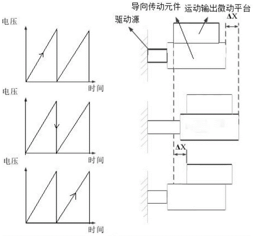
[0029] As mentioned in the background art, the micro-positioning platform based on the stick-slip principle uses flexible hinges as the guiding transmission element and piezoelectric ceramic actuators as the driving source. It has high resolution, high positioning accuracy, small size, no lubrication, and structure. The advantages of simplicity, reliability, high rigidity, low energy consumption, and fast response have gradually been widely used.

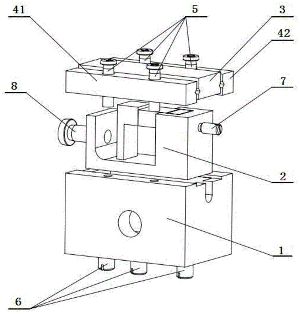
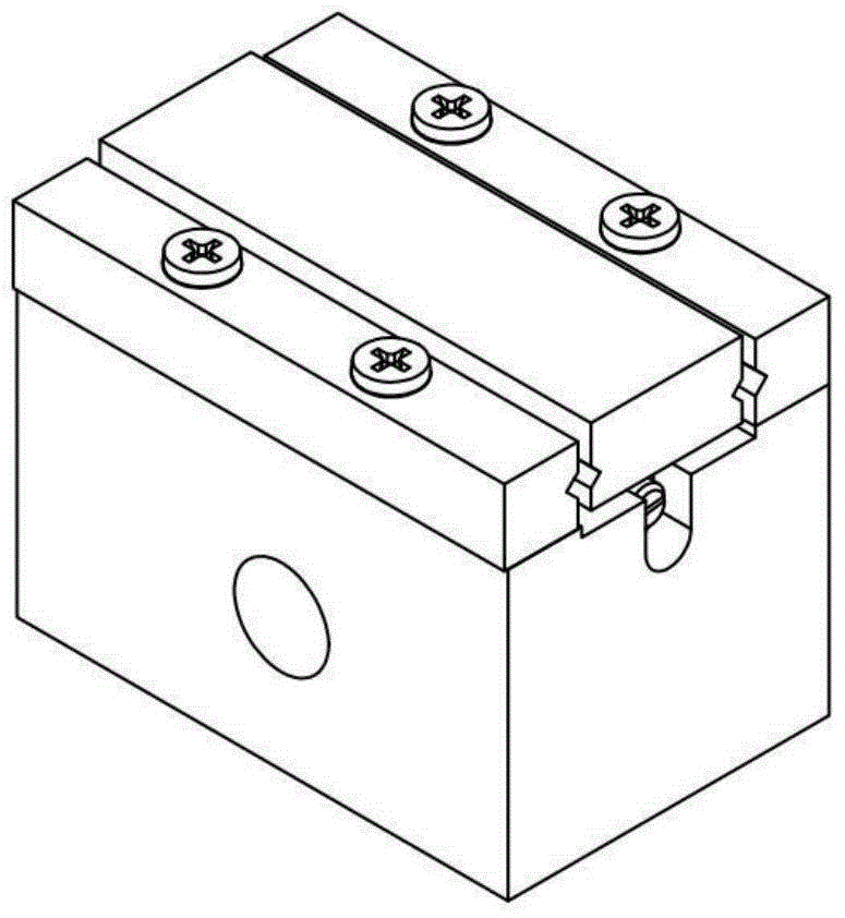
[0030] The invention discloses a modular stick-slip drive positioning platform for a drive unit, which includes a motion output micro-motion platform, a platform base and a drive unit module arranged inside the platform base. The drive unit module includes a module frame and is arranged in the module frame The guide transmission element and the drive source connected to the upper end of the guide transmission element, the guide transmission element is a flexible hinge, the top of the upper end of the guide transmission element is in con...


PUM


Abstract

The invention discloses a driving unit modularization stick-slip driving positioning platform which comprises a movement output micro-positioning platform, a platform base and a driving unit module arranged inside the platform base. The driving unit module comprises a module frame, a driving source and a guiding driving element, wherein the driving source is arranged inside the module frame, and the guiding driving element is connected with the driving source and is a flexible hinge. The guiding driving element is perpendicular to the movement output micro-positioning platform. The top of the guiding driving element makes direct contact with the movement output micro-positioning platform. The stick-slip effect is generated between the guiding driving element and the movement output micro-positioning platform, displacement is directly output, the precision is high, and the response speed is high; due to the modularized design, the platform base and the friction adjusting mechanism are greatly simplified, and the machining and manufacturing requirement of the whole positioning platform is lowered.

Description

Technical field [0001] The invention relates to the technical field of micro-drive precision positioning, in particular to a modular stick-slip drive positioning platform for a drive unit. Background technique [0002] With the development of nanoscience, new nanomaterials and nanostructures are gradually being explored and discovered, and they have shown very broad application prospects. Nanotechnology is one of the basic means for human beings to explore, understand, transform and utilize the microcosm. Among them, nanomanipulation is an important content of nanotechnology. As one of the key technologies in the micro field, the development level of micro-positioning technology directly affects the development level of the micro field technology, and its importance is self-evident. At present, such as bioengineering, polymer manipulation, minimally invasive surgery, scanning probe microscope (SPM), atomic force microscope (AFM), scanning electron microscope (SEM), microfabricat...

Claims


Application Information

Patent Timeline
Patent Type & Authority Patents(China)
IPC IPC(8): B82B3/00F16M11/04H02N2/04
Inventor 汝长海杨飞雨潘鹏王勇
Owner JIANGSU JICUI MICRO NANO AUTOMATION SYST & EQUIP TECH RES INST CO LTD
Why Eureka
Try Eureka