Energy-saving heating network heater

A heat network heater and water heating technology, which is applied to the types of heat exchangers, heat exchanger shells, indirect heat exchangers, etc., can solve the problem of damage to the support of heat exchange tubes and support plates, rising condensed water temperature, and steam Problems such as high inlet flow rate, to ensure the safety of equipment operation, reduce the steam flow rate, and achieve the effect of large heat exchange area

Inactive Publication Date: 2015-08-26
SHANDONG GUOSHUN PRESSURE VESSEL
View PDF5 Cites 10 Cited by
  • Summary
  • Abstract
  • Description
  • Claims
  • Application Information

AI Technical Summary

Problems solved by technology

[0005] 2. Since the cylinder is enlarged in the middle, it is necessary to add a support ring to support the support plate, which increases the material cost;
[0006] 3. The steam inlet flow rate is high, which has a large impact on the heat exchange tube, often causing damage to the welded joint between the heat exchange tube and the tube sheet, and the support between the heat exchange tube and the support plate;
[0007] 4. The steam inlet flow rate is high, resulting in high operating noise;
[0008] 5. Since the steam surrounds the tube bundle as a whole, the steam is in direct contact with the lower condensed water, which is equivalent to the mixed heating of steam and water, which increases the temperature of the condensed water and causes energy waste. To ensure the outlet temperature of the condensed water, it is necessary to increase the heat exchange area. cause waste of materials;
[0009] 6. The heat transfer effect is poor and the floor space is large

Method used


Image

  • Energy-saving heating network heater
  • Energy-saving heating network heater
  • Energy-saving heating network heater

Examples


Embodiment Construction

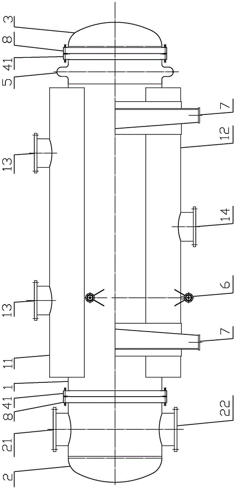
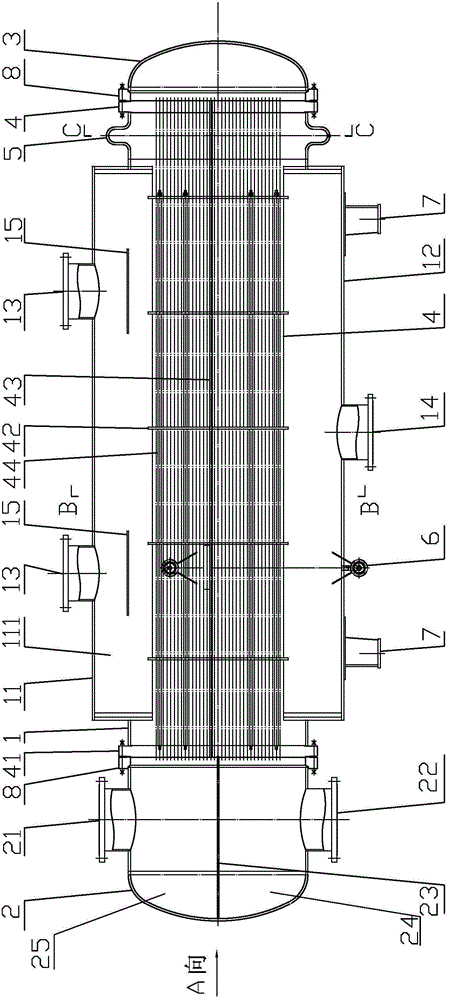
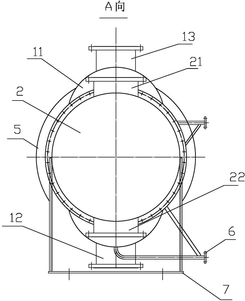
[0040] Refer to the attached figure 1 To attach Figure 7 The energy-saving heating network heater of the present invention will be described in detail below.

[0041] The energy-saving heating network heater of the present invention has a structure comprising a shell 1, a front end tube box 2, a rear end tube box 3 and a tube bundle 4, the front end tube box 2 is arranged on the front part of the shell 1, and the rear end tube box 3 is arranged on the At the rear of the shell 1, the tube bundle 4 is arranged in the shell 1, and the upper and lower parts of the front end tube box 2 are respectively provided with a heated water outlet connecting pipe 21 and a heated water inlet connecting pipe 22, and the shell 1 is a cylinder The upper and lower parts of the housing 1 are respectively provided with a steam buffer enclosure 11 and a hydrophobic storage enclosure 12. The sections of the steam buffer enclosure 11 and the hydrophobic storage enclosure 12 are respectively arc-shap...


PUM


Abstract

The invention discloses an energy-saving heating network heater which belongs to heat exchangers. The structure of the energy-saving heating network heater comprises a housing, a front end channel, a back end channel and a pipe bundle. The upper portion and the lower portion of the housing are respectively provided with a steam cushioning jacket and a lyophobic storage jacket. A steam inlet pipe is arranged at the upper portion of the steam cushioning jacket; and a lyophobic outlet pipe is arranged at the lower portion of the lyophobic storage jacket. A scour-prevention plate is arranged at the lower portion of the steam inlet pipe. A split-ranging partitioning plate is arranged in the middle of the front end channel. The pipe bundle comprises a pipe plate, a support plate, a pull rod and heat-exchanging pipes. A plurality of heat-exchanging pipes is entirely distributed all over the pipe plate. An expansion joint is arranged between the housing and the back end channel. A steam stop plate is arranged inside the expansion joint. By entirely distributing the heat-exchanging pipes all over the pipe plate, the steam is prevented from directly contacting with the condensed water, and accordingly the heat-exchanging area is increased, the temperature of the condensed water is low, thereby saving the energy source. The energy-saving heating network heater is characterized in reducing the flow speed at the steam inlet, avoiding the damage to the equipment, reducing the operation noise, and being good in heat transfer effect, or the like.

Description

technical field [0001] The invention relates to a heat exchanger, in particular to an energy-saving heating network heater. Background technique [0002] At present, most of the central heating stations in urban heating networks are steam-water shell-and-tube heating network heaters. Traditional heating network heaters use half-wave expansion joints. When using them, the entire expansion joint needs to be cut off from the middle to use them. To reduce the flow rate of steam entering the tube bundle, it is necessary to enlarge the cylinder in the middle. After the steam enters the large cylinder, it surrounds the heat exchange tube bundle for heat exchange. In order to enable the steam to enter the tube bundle effectively and avoid insufficient heat exchange at the center of the tube bundle, it is necessary to install steam on the tube plate. aisle. [0003] There are following disadvantages in existing scheme: [0004] 1. Since the steam channel is set on the tube plate, t...

Claims


Application Information

Patent Timeline
Patent Type & Authority Applications(China)
IPC IPC(8): F28D7/16F28F9/00F28F9/013
Inventor 张爱军
Owner SHANDONG GUOSHUN PRESSURE VESSEL
Why Eureka
Try Eureka