Method improving radar active beacon machine precision

A beacon and radar technology, which is applied to radar signal detection technology in radar active calibration technology, improves the accuracy of radar active beacons, and can solve the problems of reduced calibration accuracy, jitter of beacon reference signals, etc. Improve the calibration accuracy and the effect of improving calibration accuracy

Inactive Publication Date: 2015-08-26
YANGZHOU YUAN ELECTRONICS TECH CO LTD
View PDF4 Cites 3 Cited by
  • Summary
  • Abstract
  • Description
  • Claims
  • Application Information

AI Technical Summary

Problems solved by technology

Therefore, the beacon machine using the linear detection amplification technology directly causes the jitter of the

Method used


Image

  • Method improving radar active beacon machine precision
  • Method improving radar active beacon machine precision
  • Method improving radar active beacon machine precision

Examples


Embodiment Construction

[0022] The present invention will be described in further detail below in conjunction with accompanying drawing

[0023] A method for improving the accuracy of radar active beacons. This method uses logarithmic detection to process received interrogation signals, reduces changes in radar transmission and reception power due to weather and temperature changes, and significantly improves calibration accuracy. The specific requirements are as follows :

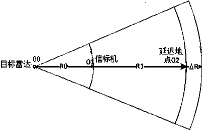
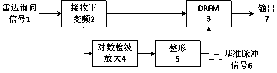
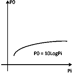
[0024] 1) The target radar sends out an inquiry signal, and the beacon machine receives the inquiry signal, and then down-converts it to an intermediate frequency signal. On the one hand, the intermediate frequency signal is input into DRFM for calculation and processing; on the other hand, the intermediate frequency signal is subjected to logarithmic detection and amplification; the logarithmic detection method, The input signal amplitude Pi has a logarithmic relationship with the output signal amplitude P0, P0=10LogPi, after lo...


PUM


Abstract

The invention discloses a method improving radar active beacon machine precision; the method comprises the following steps: using a logarithm detection mode to process and receive an inquiry signal; shaping the signal and outputting a pulse signal to serve as a reference signal for a DRFM; reducing radar emitting and receiving power changes caused by the temperature and weather change factors, thus obviously improving alignment calibration precision. The method uses the logarithm demodulation mode to process and receive the inquiry signal, can effectively reduce radar emitting and receiving power changes caused by the temperature and weather change factors, and can prevent shaking phenomenon of pulse front edge after demodulation, thus obviously improving alignment calibration precision, and a distance precision can reach precision requirements needed by a fire control radar for alignment calibration.

Description

technical field [0001] The invention relates to a radar active calibration technology, in particular to a radar signal detection technology in the radar active calibration technology. Specifically, a method for improving the accuracy of radar active beacons. Background technique [0002] For existing radar active beacons, buildings or other obstacles may appear around the beacon, resulting in a lot of noise on the radar screen, so that it is impossible to distinguish the real target. Therefore, usually the beacon machine adopts the method of converting the delay time into a distance and superimposing it, so as to transfer the marking point of the beacon machine to a place with a clean background, which is convenient for the radar to find the marking point. [0003] Such as figure 1 As shown, it is assumed that the target radar position is 00, the radar active beacon position is 01, and the delay point is 02. The distance between the target radar and the radar active beaco...

Claims


Application Information

Patent Timeline
IPC IPC(8): G01S7/28
CPCG01S7/28
Inventor 袁冬青徐冬亮李继峰万士强
Owner YANGZHOU YUAN ELECTRONICS TECH CO LTD
Why Eureka
Try Eureka