Motor

A voltage and current technology, applied in the field of electricity, can solve the problems of adjustment, inability to realize the sine wave current phase, increase the production cost of the motor and the failure rate of the motor, and achieve the effect of simplifying the motor process

Active Publication Date: 2015-08-26
LUYUAN ELECTRIC VEHICLE SHANDONG
View PDF8 Cites 2 Cited by
  • Summary
  • Abstract
  • Description
  • Claims
  • Application Information

AI Technical Summary

Problems solved by technology

[0002] At present, in the related art, Hall sensors are installed in the motor to detect the position of the rotor of the motor relative to the stator, and the commutation output of the motor is determined according to the detected position signal, which not only increases the complexity of the process of producing the motor It also increases the production cost of the motor and the failure rate of the motor. In addition, the non-Hall detection technology in the related art determines the position of the rotor relative to the stator by detecting the back electromotive force of the three-phase winding of the stator, so that it can be detected according to the position to adjust the phase of the current flowing into the stator, however, the non-Hall detection technology in the related art can only adjust the phase of the square wave current flowing into the stator, and cannot adjust the phase of the sine wave current

Method used


Image

  • Motor
  • Motor
  • Motor

Examples


Embodiment Construction

[0028] In order to understand the above objects, features and advantages of the present invention more clearly, the present invention will be further described in detail below with reference to the accompanying drawings and specific embodiments. It should be noted that the embodiments of the present application and the features in the embodiments may be combined with each other in the case of no conflict.

[0029] Many specific details are set forth in the following description to facilitate a full understanding of the present invention. However, the present invention can also be implemented in other ways different from those described herein. Therefore, the protection scope of the present invention is not limited by the specific details disclosed below. Example limitations.

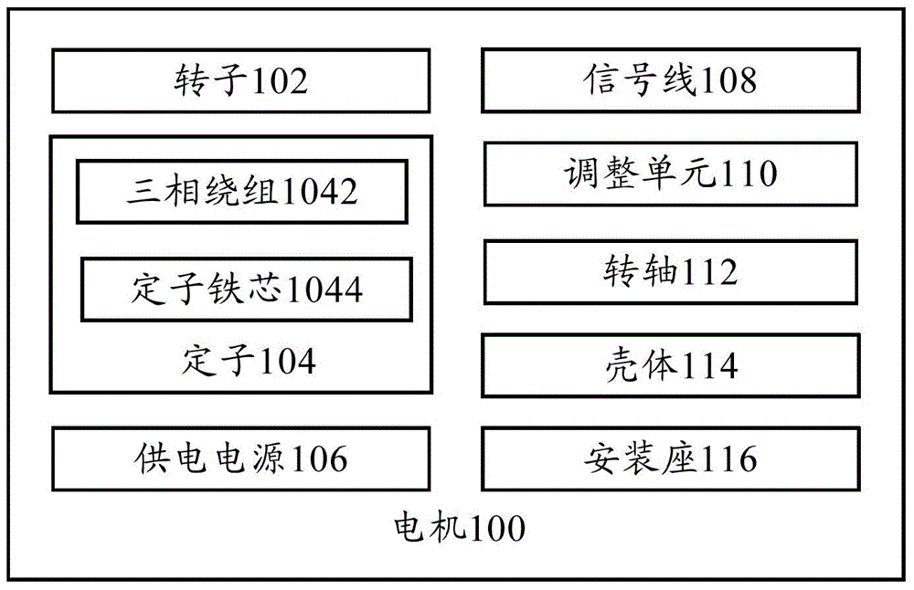
[0030] figure 1 A schematic structural diagram of a motor according to an embodiment of the present invention is shown.

[0031] like figure 1 As shown, the motor 100 according to an embodiment of the...


PUM


Abstract

The invention provides a motor which comprises a rotor, a stator, a power supply, a signal line and an adjusting unit, wherein the stator comprises a three-phase winding connected in a star-shaped manner; the power supply is connected to the rotor and the stator, and is used for supplying power to the rotor and the stator; one end of the signal line is connected to the neutral point of the three-phase winding; the signal line is used for detecting the back electromotive force of the three-phase winding; the adjusting unit is connected to the other end of the signal line, and is used for determining the relative position of the rotor relative to the stator according to the back electromotive force and the voltage of the power supply to adjust the phase position of the current flowing into the stator according to the relative position. Through the technical scheme, the back electromotive force of the three-phase winding of the stator is detected more accurately through the signal line, so that the relative position of the rotor relative to the stator is determined more accurately according to the back electromotive force instead of a Hall sensor in the correlation technique, the motor process is simplified, and besides, the phase position of the sine-wave current flowing into the stator can be adjusted.

Description

technical field [0001] The present invention relates to the technical field of electricity, in particular, to a motor. Background technique [0002] At present, in the related art, a Hall sensor is installed in the motor to detect the position of the rotor of the motor relative to the stator, and the commutation output of the motor is determined according to the detected position signal, which not only increases the complexity of the production process of the motor In addition, the Hall-free detection technology in the related art determines the position of the rotor relative to the stator by detecting the back electromotive force of the three-phase winding of the stator, so that the position of the rotor relative to the stator can be determined according to the detected However, the non-Hall detection technology in the related art can only adjust the phase of the square wave current flowing into the stator, but cannot adjust the phase of the sine wave current. [0003] The...

Claims


Application Information

Patent Timeline
Patent Type & Authority Applications(China)
IPC IPC(8): H02K11/00H02P6/18
Inventor 倪捷胡继红陈文胜吴启皇姚国柱周湛晨
Owner LUYUAN ELECTRIC VEHICLE SHANDONG
Why Eureka
Try Eureka