Resonance-type large-power multipath output LED drive power supply

A LED drive and multi-output technology, which is applied in the direction of electric light source, light source, lamp circuit layout, etc., can solve the problems of simultaneous dimming of multiple channels, the number of parallel LED strings cannot be increased or decreased at will, and high cost, so as to reduce mutual interference Effect

Inactive Publication Date: 2015-08-26
XIAN JIAOTONG LIVERPOOL UNIV
View PDF6 Cites 2 Cited by
  • Summary
  • Abstract
  • Description
  • Claims
  • Application Information

AI Technical Summary

Problems solved by technology

In most applications, it is necessary to drive multiple high-power LED devices at the same time. Considering the difference in the voltage and current characteristics of a single LED, it is easy to cause current imbalance between LED strings connected in parallel.
[0003] The current LED drive power supply provides independent driving power for each LED branch to achieve constant current output of each branch. This method has high cost and low efficiency. When a branch fails, the current re-sharing control is complex and the system reliability is low

Method used


Image

  • Resonance-type large-power multipath output LED drive power supply
  • Resonance-type large-power multipath output LED drive power supply
  • Resonance-type large-power multipath output LED drive power supply

Examples


Embodiment 1

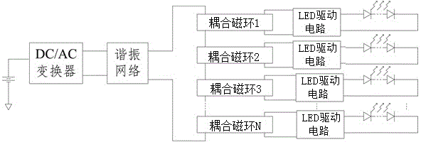
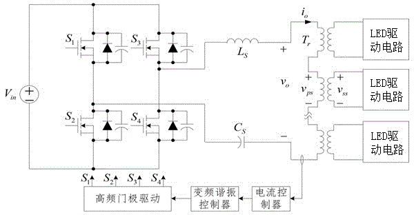
[0026] like figure 2 It is shown that the DC / AC converter is a high -frequency DC / AC inverter. The high -frequency DC / AC inverter uses the full bridge circuit composed of the four power MOSFETs of S1, S2, S3, and S4The output end of the AC inverter is connected to the resonant circuit, which is a CL single -stage resonance circuit composed of an inductive LS and a capacitor CS. There are several coupled magnetic rings TR on the resonance circuit.The output is connected to an LED drive circuit.The coupling cycagenic ring coupling is an iron oxygen magnetic ring or an amorphous ring.

[0027] The resonant network output terminal connects the current controller, the inverter resonance controller, and the high -frequency door -driven circuit, the current controller is compared with the input current of the coupling magnetic ring.Polar drive circuit control adjustment DC / AC inverter circuit frequency or duty occupation ratio.

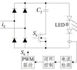
[0028] like image 3 It shows that the LED driver circuit i...

Embodiment 2

[0031] like Figure 4 It is shown that the DC / AC converter is a high -frequency DC / AC inverter. Unlike Example 1, the high -frequency DC / AC inverter is composed of capacitor C1, C2 and power MOSFET S1, S2.Half -bridge single topology.Other structures are the same as Example 1.Similarly, the current controller is compared with the input current of the coupling magnetic ring, and the frequency frequency frequency frequency resonance controller and the high -frequency door -driven circuit control the DC / AC inverter circuit frequency or duty cycle by the reference current.The LED drive circuit still uses embodiment 1 image 3 The structure shown.

Embodiment 3

[0033] like Figure 5 The DC / AC converter is a high -frequency DC / AC inverter, and the high -frequency DC / AC inverter uses a boost circuit connected in turn and two -level topology of the full bridge circuit.The resonance network uses the CL-CL two-level resonance circuit.The boost circuit includes the power MOSFET S1, the inductance LO, and the diode D1, and the full bridge circuit consists of the four power MOSFETs: S2, S3, S4, and S5.The CL-CL two-level resonance circuit is composed of inductive inductors L1, L2 and capacitance C1, C2. There are several coupling magnetic rings TR on the resonant circuit.Circuit still adopts embodiment 1 image 3 The structure shown.The coupling cycagenic ring coupling is an iron oxygen magnetic ring or an amorphous ring.

[0034] The resonant network output terminal connects the current controller, the constant frequency pulse width controller, and the high -frequency door pole drive circuit.The voltage circuit occupy the duty ratio to adjust the...


PUM


Abstract

The invention discloses a resonance-type large-power multipath output LED drive power supply, and the power supply comprises a DC / AC converter and a resonance network, which are connected sequentially. The output end of the resonance network is in series connection with a plurality of coupling magnetic rings, and the secondary side of each coupling magnetic ring is connected with an LED driving circuit. The output end of each LED drive circuit is connected with a drive LED string. The output end of the resonance network samples the input current of the coupling magnetic rings through a primary-current closed-loop control circuit. The input current is compared with a reference current, and then the power or duty ratio of the DC / AC converter is controlled. The LED drive circuit at a secondary side of each coupling magnetic ring comprises a diode rectification circuit and a capacitor charging circuit. A current detection circuit connected with the output end of each LED drive circuit detects the output current of the corresponding LED string, and the power and duty ratio of the capacitor charging circuit is controlled in a closed-loop manner, thereby achieving the constant-current output of the LED strings. The number of parallel LED strings can be changed freely, and the mutual interference between the LED strings is reduced.

Description

Technical field [0001] The present invention involves LED -drive power supply, which especially involves a resonant high -power multi -way output LED drive power supply. Background technique [0002] Compared with incandescent lamps, fluorescent lamps, and high -intensity gas discharge lamps compared to incandescent lamps, fluorescent lamps, and high -strength gas discharge lamps, they are known as "green light sources".LED has a positive turnover working voltage, and the tiny fluctuation of the turning voltage will cause a significant increase in the positive average current.Streaming driver; LED is a one -way conductive device that needs to be powered by DC current or one -way pulse current; the current and optical flux of the flowing of the LED shows non -linear characteristics. The LED should work as much as possible under the current value of high luminous efficiency.In most applications, multiple high -power LED devices need to be driven at the same time. Considering that t...

Claims


Application Information

Patent Timeline
Patent Type & Authority Applications(China)
IPC IPC(8): H05B37/02
Inventor 文辉清
Owner XIAN JIAOTONG LIVERPOOL UNIV
Why Eureka
Try Eureka