A Turbine Guide Vane Automatic Spraying Support Protection Fixture

A turbine guide vane and automatic spraying technology, applied in the direction of spraying devices, etc., can solve the problems of inability to guarantee the consistency of blade coating quality and unstable process parameters, etc., and achieve the goals of reducing equipment working time, strong flexibility, and saving time Effect

Active Publication Date: 2017-04-19
AECC AVIATION POWER CO LTD
View PDF5 Cites 2 Cited by
  • Summary
  • Abstract
  • Description
  • Claims
  • Application Information

AI Technical Summary

Problems solved by technology

Due to the influence of operator experience and subjectivity, process parameters such as spray gun moving speed and spraying distance cannot be stabilized within the limits of process requirements, and the quality consistency of each blade coating cannot be guaranteed

Method used


Image

  • A Turbine Guide Vane Automatic Spraying Support Protection Fixture
  • A Turbine Guide Vane Automatic Spraying Support Protection Fixture
  • A Turbine Guide Vane Automatic Spraying Support Protection Fixture

Examples


Embodiment Construction

[0022] The process fixture described in the present invention is a special tool, so only the installation implementation of this type of guide vane is listed below.

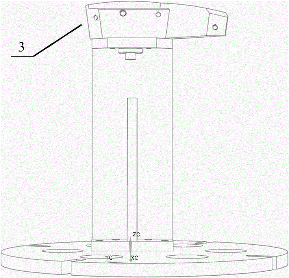
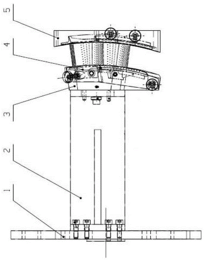
[0023] A turbine guide vane automatic spraying support and protection fixture, characterized in that it includes a base 1, a support plate 2, a positioning block 3, a lower baffle 4, an upper baffle 5,

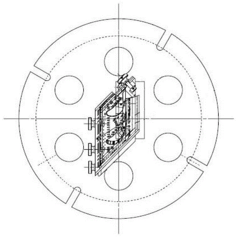
[0024] The base 1 is disc-shaped, with cross grooves arranged in the circumferential direction, fixed to the center of the turntable with bolts,

[0025] The support plate 2 is installed vertically on the base 1, and the top of the support plate 2 is a plane;

[0026] The positioning block 3 is a V-shaped plate structure with an opening forward to install the guide vane. The bottom surface of the positioning block 3 is installed on the top plane of the support plate 2 through bolts. The shape of the installation edge matches, and the upper edge of the positioning block 3 is flush with the height of the sprayed e...


PUM


Abstract

The invention provides an automatic spraying support protection fixture for turbine guide vanes. The automatic spraying support protection fixture is characterized by comprising a base (1), a supporting plate (2), a positioning block (3), a lower baffle (4) and an upper baffle (5). The supporting plate (2) is perpendicularly installed on the base (1), and the top end of the supporting plate (2) is provided with a plane; the positioning block (3) is of a V-shaped plate structure with a forward opening and is used for installing the guide vanes, the bottom surface of the positioning block (3) is installed on the plane of the top end of the supporting plate (2) through bolts, an opening installation surface of the positioning block (3) is matched with installation edges of the vane back sides of lower edge plates of the guide vanes in shape, and the upper edge of the positioning block (3) is flush with the spraying end faces of the lower edge plates of the guide vanes; the lower baffle (4) is of a V-shaped plate structure with a backward opening, an opening part installation surface of the lower baffle (4) is matched with the vane basin sides of the lower edge plates of the guide vanes in shape, and the upper edge of the lower baffle (4) is flush with the spraying end faces of the lower edge plates of the guide vanes.

Description

[0001] Technical field: [0002] The invention belongs to the surface coating protection technology, and relates to the design of the supporting protection tooling required for the automatic spraying of the turbine guide blades of the aero-engine. [0003] Background technique: [0004] As the core component of the engine, the turbine vane assembly of the aero-engine needs to be sprayed with a thermal barrier coating on the surface. Its structure is a double-connected blade, and there is mutual interference and shielding between the front and rear blades and the upper and lower edge plates, and the structure is complex. Restricted by the part structure, the factory has long been painting by hand. However, when spraying manually, the part is placed directly on the operating platform, and the operator rotates or reverses the part after spraying one surface, and then sprays the other surface. Due to the influence of operator experience and subjectivity, process parameters such a...

Claims


Application Information

Patent Timeline
Patent Type & Authority Patents(China)
IPC IPC(8): B05B13/02B05B15/04
CPCB05B12/28B05B13/0285
Inventor 张会盈胡江波王斌利姚妮黄宝庆王建锋田雅旭牛阿妮
Owner AECC AVIATION POWER CO LTD
Why Eureka
Try Eureka