a hydroelectric generator

A hydro-generator and hydro-wheel technology, which is applied in the directions of hydro-electric power generation, engine components, impact engines, etc., can solve the problems of low utilization rate of impact water flow, inability to use pipelines, and large rotational resistance of the runner, and improve the specific speed. and power generation efficiency, easy compression and diffusion, and the effect of reducing rotational resistance

Active Publication Date: 2019-04-09
NINGBO RUNQIAO IND DESIGN CO LTD
View PDF9 Cites 0 Cited by
  • Summary
  • Abstract
  • Description
  • Claims
  • Application Information

AI Technical Summary

Problems solved by technology

[0002] The small flow rate of tap water pipelines is not suitable for impact hydro-generators. Traditional impact hydro-generators can only be used at the terminal, and the tail water pressure and flow rate are lost, so they cannot be used in pipelines.
Chinese Patent Publication No. CN 101825051 A discloses a technical scheme of a water pipe power generation device. The flow channel in the water wheel chamber is composed of a vertically arranged cylindrical cavity connected tangentially to an annular cavity with a horizontal axis. The impacting water flows from the cylindrical The upper port of the cavity enters, and the lower port flows out. This scheme has the disadvantages of low impact water velocity, low utilization rate of impact water flow, and large resistance of water in the annular cavity when the runner rotates.
China Patent No. 201510109582.1 discloses a technical solution of a hydroelectric generator, which overcomes the shortcomings of the previous technical solution, such as low impact water velocity and low utilization rate of impact water flow, but the disadvantage of large rotation resistance of the runner still exists

Method used


Image

  • a hydroelectric generator
  • a hydroelectric generator
  • a hydroelectric generator

Examples


Embodiment

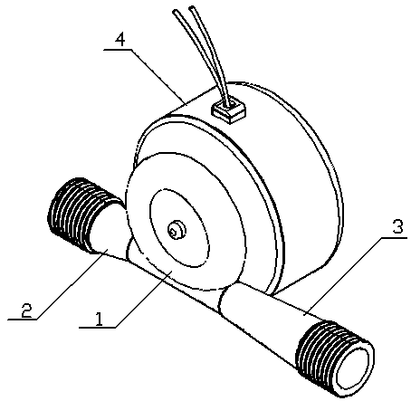
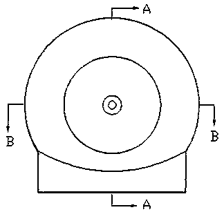
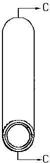
[0017] See attached Figure 1-9 , the present embodiment includes a water wheel chamber 1, a power generation chamber 4, a water guide pipe 2 and a draft pipe 3 connected with the water wheel chamber, and a runner 5 is arranged in the water wheel chamber 1, and the water wheel chamber 1 is formed by an annular cavity 1.1 is tangentially connected with the cylindrical cavity 1.2, wherein the annular cavity 1.1 is on the top, and the cylindrical cavity 1.2 is on the bottom, so that the gas is kept in the annular cavity 1.1, and the centerline of the annular cavity 1.1 and the cylindrical cavity The axes of 1.2 are in the same plane and are tangent to each other. Two air grooves 1.3 and 1.4 are provided on the inner wall of the annular cavity 1.1 for the gas in the cavity to move in the opposite direction relative to the water bucket 5.2 when the runner 5 rotates. The centerlines of the gas grooves 1.3 and 1.4 are C-shaped, and the two ends thereof are kept at a distance of about...


PUM


Abstract

The invention provides a tap water pipeline generator capable of significantly reducing rotation resistance of a rotating wheel. The technical scheme is as follows: the hydro-generator comprises a water wheel chamber, a generation chamber, a water guide pipe and a tail water pipe, wherein the rotating wheel is arranged in the water wheel chamber and comprises a wheel disk and a water bucket, a runner of the water wheel chamber is formed by tangency of an annular cavity surrounding the water bucket and a cylindrical cavity, the inner diameter of the annular cavity is slightly larger than the outer diameter of the water bucket, the diameter of the cylindrical cavity is equal to that of the annular cavity, and the annular cavity is located on the cylindrical cavity and filled with gas. Gas grooves are formed in the inner wall of the annular cavity. The flowability of gas is better than that of a liquid, and the gas can move relative to the rotating wheel in the gas grooves more easily during rotation of the rotating wheel, therefore, compared with the prior art, the hydro-generator has the benefits that the rotation resistance of the rotating wheel is significantly reduced and the specific speed and the generation efficiency are improved.

Description

technical field [0001] The invention relates to a water turbine generator, in particular to a water turbine generator that can be connected to a tap water pipeline. Background technique [0002] The small flow rate of the tap water pipeline is not suitable for the impact hydro-generator. The traditional impact hydro-generator can only be used in the terminal, and the pressure and flow velocity of the tail water are lost, so it cannot be applied in the pipeline. Chinese Patent Publication No. CN 101825051 A discloses a technical scheme of a water pipe power generation device. The flow channel in the water wheel chamber is composed of a vertically arranged cylindrical cavity connected tangentially to an annular cavity with a horizontal axis. The impacting water flows from the cylindrical The upper port of the cavity enters and the lower port flows out. This scheme has the disadvantages of low impact water flow velocity, low utilization rate of impact water flow, and greater re...

Claims


Application Information

Patent Timeline
Patent Type & Authority Patents(China)
IPC IPC(8): F03B13/00F03B1/00F03B1/02
CPCY02E10/20
Inventor 芦雷
Owner NINGBO RUNQIAO IND DESIGN CO LTD
Why Eureka
Try Eureka