Quick valve

A shutter and valve port technology, applied in the direction of lift valve, valve details, valve device, etc., can solve the problems of severe wear, large frictional resistance, increased pressure loss, etc., and achieve high sealing reliability, zero pressure loss, and no operation. wear effect

Active Publication Date: 2015-09-02
王淑萍
View PDF10 Cites 7 Cited by
  • Summary
  • Abstract
  • Description
  • Claims
  • Application Information

AI Technical Summary

Problems solved by technology

[0004] The disadvantages of patent WO2012042255A1 valve are very obvious: 1. The contact surface between the rotor and the stator is a cylindrical surface, and the sealing performance is poor. If no leakage is required, the processing accuracy of the outer cylindrical surface of the rotor and the inner cylindrical surface of the stator is extremely high, and the processing is very difficult. Big
2. Preload cannot be applied in the radial direction, and sealing reliability is difficult to guarantee
3. To ensure reliable sealing, the gap between the outer cylindrical surface of the rotor and the inner cylindrical surface of the stator must be very small, which will cause a large friction force when the rotor and the stator rotate with each other. On the one hand, the rotation resistance will be large, and a larger torque is required. Affected switching speed
At the same time, the mutual wear is severe. As the service time increases, the gap will become larger and larger, which will directly affect the seal.
4. In order to achieve no leakage between the center hole of the rotor and the center hole of the stator, the end face of the rotor must also be plane-sealed with the end face of the stator, closely fit, and able to slide each other, which further increases the driving force of the rotor. Torque, meanwhile, causes greater wear
5. The switching speed of the valve is not high, and it takes a long time for the position of the valve port to be aligned from part to full alignment, the suddenness of the airflow is not enough, and the pressure loss is increased at the same time
The second valve is easy to leak due to the gap between the valve plate and the valve body, so the depth of disturbance is limited. If the gap between the valve plate and the valve body is reduced, since the valve body and the valve plate are cylindrical surfaces, the processing is difficult , at the same time, the frictional resistance is large when disturbed
In addition, the patent US2012 / 0285460A1 uses two rotating drive components to increase the complexity and cost of the equipment

Method used


Image

  • Quick valve
  • Quick valve
  • Quick valve

Examples


Embodiment Construction

[0023] The invention is described below with reference to the drawings, in which like parts are identified with like reference numerals.

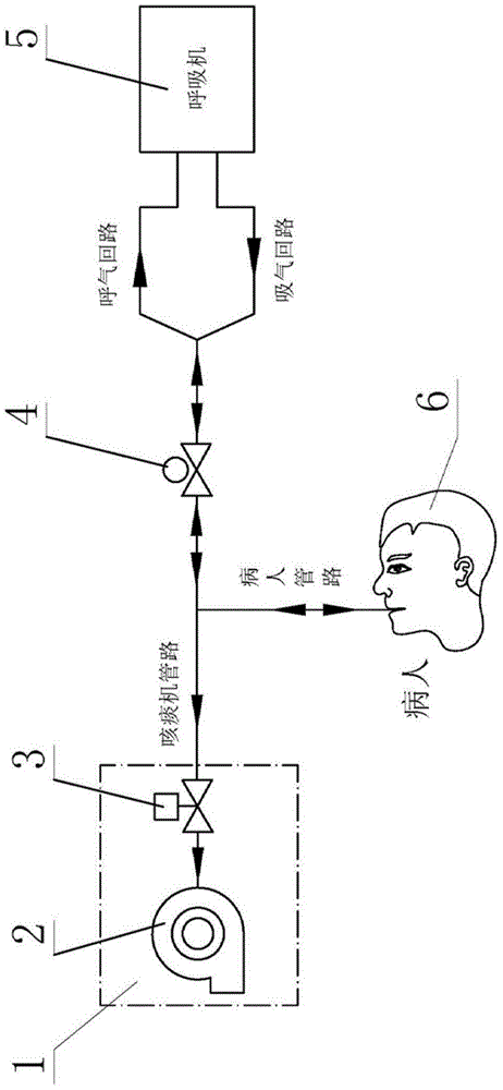
[0024] The innovation motivation of the present invention comes from the needs of a fully automatic synchronous expectoration machine. The fully automatic synchronous expectoration machine is used in ICU wards or respiratory departments. It is used in conjunction with a ventilator to automatically and instantly clear the respiratory sputum of mechanically ventilated patients by simulating human coughing. The so-called simulated patient cough means that after the ventilator gives the patient a positive pressure ventilation with a tidal volume large enough, the expectorant machine gives the patient a rapid and sudden reverse expiratory airflow. Combine below figure 1 Briefly introduce the innovative motivation of the present invention.

[0025] The expectorant machine 1, the ventilator 5 and the patient 6 are ventilated through the balloon ...


PUM


Abstract

A quick valve (3) comprises a swing member (8) and an angle adjusting member (9). The swing member (8) can be rotatingly fixed on a valve body (7), the valve body (7) has a valve port (10), the swing member (8) can rotate along the direction that clings to or far away from the valve port (10). The angle adjusting member (9) can cover the valve port (10), the angle adjusting member (9) is combined with the swing member (8), and the angle adjusting member (9) can adjust an angle between itself and the valve port (10). The quick valve is simple in structure, easy to process, high in sealing reliability, quick in switch and with no abrasion during rotation and no pressure loss.

Description

technical field [0001] The present invention relates to a valve, more particularly to a low pressure loss valve capable of fast switching. Background technique [0002] In medical devices, such as fully automatic sputum expectoration machines, valves that can be opened and closed quickly, with low pressure loss and good sealing are required. [0003] Patent WO2012042255A1 describes a valve that can be quickly switched, including a fan-shaped rotor and a stator concentric with it as a valve body. There is a central air inlet on the rotor, and the central hole of the rotor communicates with the patient's breathing circuit. At the same time, the rotor has a hole in the radial direction, which communicates with the central air inlet. The inner cylindrical surface of the stator is distributed along the circumferential direction with two holes forming a certain angle, and the two holes on the stator communicate with the air inlet and the air outlet of the fan respectively. The ...

Claims


Application Information

Patent Timeline
Patent Type & Authority Applications(China)
IPC IPC(8): F16K1/20F16K1/48F16K1/36F16K1/46F16K31/44F16K31/06F16K27/02F16K47/02A61M16/20
CPCF16K1/20F16K1/36A61M16/201A61M16/202F16K1/2007F16K1/2014F16K1/205F16K1/2085F16K27/0209F16K31/0655F16K31/44F16K47/023
Inventor 王淑萍
Owner 王淑萍
Why Eureka
Try Eureka