Polar coordinate composite camera rack for vision inspection

A technology of visual inspection and polar coordinates, which is applied in the direction of measuring devices, measuring instrument components, instruments, etc., can solve the problems of difficult to obtain images, difficult to adjust the camera position, etc., and achieve the effect of convenient disassembly and easy measurement of angle parameters

Inactive Publication Date: 2015-09-02
HUBEI UNIV OF TECH
View PDF6 Cites 26 Cited by
  • Summary
  • Abstract
  • Description
  • Claims
  • Application Information

AI Technical Summary

Problems solved by technology

[0004] The purpose of the present invention is to provide a polar coordinate composite camera frame for visual inspection, which solves the

Method used


Image

  • Polar coordinate composite camera rack for vision inspection
  • Polar coordinate composite camera rack for vision inspection
  • Polar coordinate composite camera rack for vision inspection

Examples


Embodiment Construction

[0014] The present invention will be described in detail below in combination with specific embodiments.

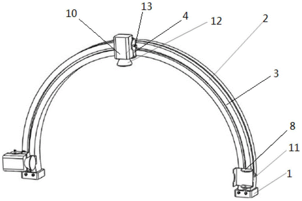
[0015] The camera frame of the present invention is a mechanical mechanism used for installation, positioning and position adjustment of industrial cameras used in image acquisition in an industrial detection system.

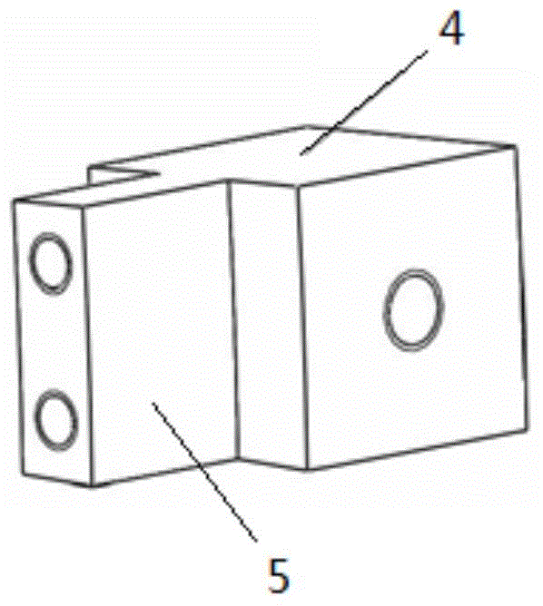
[0016] The camera frame system of the present invention includes an end cover 1 and an arc frame 2, two end caps 1 are installed on the two ends of the arc frame 2 respectively, and the end cover 1 is fixed on the work surface to support the entire arc. The role of shaped rack 2. The arc frame 2 is provided with a guide rail 3, and the slider 4 is installed in the guide rail 3. The slider 4 can slide on the arc frame 2 along the guide rail 3. The bracket fine-tuning device is fixedly connected with the slider 4, and the bracket fine-tuning device It is connected with the camera fixing bracket, and the bracket fine-tuning device adjusts the position of the ...


PUM


Abstract

The invention discloses a polar coordinate composite camera rack for vision inspection. The polar coordinate composite camera rack includes end covers and an arc-shaped rack. The two end covers are mounted on two ends of the arc-shaped rack. The end covers are fixed on a working table. The arc-shaped rack is provided with a guide rail. A slide block is mounted in the guide rail. The slide block can slide on the arc-shaped rack along the guide rail. A support fine adjustment device is connected with the slide block fixedly. The support fine adjustable device is connected with the camera fixing support. The support fine adjustment device is used for position adjustment of the camera fixing support which is used for fixing cameras. The camera rack provided by the invention has beneficial effects that the cameras are arranged in the normal direction of the arc-shaped rack and the camera quantity can be changed and the camera positions can be adjusted freely according to detection requirements and lighting modes. The rack can be mounted and dismounted conveniently and the angle parameters facilitate measurement.

Description

technical field [0001] The invention belongs to the technical field of peripheral equipment of a machine vision system, and relates to a polar coordinate composite camera frame for visual detection. Background technique [0002] Machine vision is a comprehensive technology that combines digital image processing, mechanical engineering, electronic engineering, optical engineering and software engineering. Its core is to process and analyze the collected images. In image detection, lighting conditions and camera position are two key factors that determine the quality of image acquisition, because subsequent computer image processing is very sensitive to image parameters such as brightness, reflection, and chromaticity, and the mutual adjustment of lighting methods and camera positions It determines the pros and cons of these parameters. The position of the camera can change the intensity of light and affect the brightness of the collected image, and can easily change the refl...

Claims


Application Information

Patent Timeline
IPC IPC(8): G01D11/30
Inventor 赵大兴孙国栋张杨王璜杨林杰林松王博靖马超
Owner HUBEI UNIV OF TECH
Why Eureka
Try Eureka