Light Filter, Optical Module, And Electronic Device

A technology of electronic equipment and optical filters, applied in optics, optical components, instruments, etc., can solve problems such as stress difference

Inactive Publication Date: 2015-09-02
SEIKO EPSON CORP
View PDF7 Cites 0 Cited by
  • Summary
  • Abstract
  • Description
  • Claims
  • Application Information

AI Technical Summary

Problems solved by technology

In Patent Document 1, although the reflective film is sandwiched between the base film and the protective film, no countermeasures are taken against the stress difference between the two surfaces.

Method used


Image

  • Light Filter, Optical Module, And Electronic Device
  • Light Filter, Optical Module, And Electronic Device
  • Light Filter, Optical Module, And Electronic Device

Examples


no. 1 approach

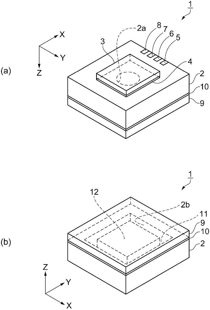
[0058] In this embodiment, an optical module having a characteristic structure and a method of manufacturing the optical module will be described with reference to the drawings. refer to Figure 1 to Figure 8 , to describe the optical module. figure 1 (a) and figure 1 (b) is a schematic perspective view showing the structure of the optical module. figure 1 (a) is a view viewed from the first cover side of the optical module, figure 1 (b) is a view seen from the second cover side of the optical module. Such as figure 1 As shown in (a), the optical module 1 has a substantially rectangular parallelepiped shape. Let the downward direction in the figure of the optical module 1 be the Z direction, and let the two directions perpendicular to the Z direction be the X direction and the Y direction. The X direction, the Y direction, and the Z direction are directions along the sides of the optical module 1 , which are orthogonal directions.

[0059] The optical module 1 includes ...

no. 2 approach

[0144] Next, use Figure 9 and Figure 10 One embodiment of an optical module will be described. Figure 9 (a) is a schematic plan view showing the structure of the movable substrate, Figure 9 (b) is a schematic plan view showing the structure of the fixed substrate. Figure 10 It is the electrical control block diagram of the control part. This embodiment differs from the first embodiment in that the movable reflective film 35 and the fixed reflective film 44 are electrically connected within the filter. In addition, descriptions of the same points as those in the first embodiment are omitted.

[0145] That is to say, in this embodiment, if Figure 9 As shown, the optical module 60 includes an optical filter 61 in which the movable substrate 13 and the fixed substrate 14 are bonded via the bonding film 30 . A conductive film 32 is provided on the movable substrate 13 , and a movable reflective film 35 and a protective film 36 are provided to overlap on the conductive f...

no. 3 approach

[0153] Next, use Figure 11 A first embodiment of the optical module will be described. Figure 11 This is a schematic sectional view of main parts showing the structure of the reflective film. This embodiment differs from the first embodiment in that the materials of the conductive film and the protective film are different. In addition, descriptions of the same points as those in the first embodiment are omitted.

[0154] That is to say, in this embodiment, if Figure 11 As shown, the optical module 66 includes an optical filter 67 in which the movable substrate 13 and the fixed substrate 14 are bonded via the bonding film 30 . A conductive film 68 is provided on the movable substrate 13 , and the movable reflection film 35 and the protective film 69 are provided to overlap on the conductive film 68 . The conductive film 70 is provided on the fixed substrate 14 , and the fixed reflective film 44 and the protective film 71 are provided to overlap on the conductive film 70...


PUM


Abstract

A light filter includes a fixed substrate (14), a movable portion (13) which is arranged to face the fixed substrate, a fixed reflective film (44) which is disposed in the fixed substrate, and reflects a part of light and transmits a part of the light, a movable reflective film (35) which is disposed in the movable portion to face the fixed reflective film, and reflects a part of the light and transmits a part of the light, and an electrostatic actuator which controls a distance between the fixed reflective film and the movable reflective film, the fixed reflective film is interposed between a conductive film (32) and a protective film (36), and the conductive film and the protective film are formed of the same material, and have the same film thickness. Then, the movable reflective film is interposed between a conductive film and a protective film, and the conductive film and the protective film are formed of the same material, and have the same film thickness.

Description

[0001] This application is based on the contents of Japanese Patent Application No. 2014-038179 filed on February 28, 2014, the entire contents of which are hereby incorporated by reference. technical field [0002] The invention relates to an optical filter, an optical module and electronic equipment. Background technique [0003] Currently, an optical filter is used that selects light of a specified wavelength from incident light and passes it through. Furthermore, Patent Document 1 discloses an optical filter that passes light of a predetermined wavelength. In this optical filter, a pair of substrates are opposed to each other, and reflective films are respectively provided on opposing surfaces of the substrates. [0004] This optical filter selectively extracts light having a wavelength corresponding to a gap between a pair of opposing reflective films. The gap between the reflection films is set by the thickness of the separation film provided between the substrates. ...

Claims


Application Information

Patent Timeline
Patent Type & Authority Applications(China)
IPC IPC(8): G02B26/00
CPCG02B26/001G02B1/14G02B1/16
Inventor 新东晋北原浩司坂下友树
Owner SEIKO EPSON CORP
Why Eureka
Try Eureka