
Air quality prediction method and device

A technology for air quality and time prediction, applied in special data processing applications, instruments, electrical digital data processing, etc., can solve problems such as difficulty in implementation, high computing resources, and low accuracy of air quality data.

Active Publication Date: 2015-09-02
象辑科技股份有限公司
View PDF3 Cites 19 Cited by
  • Summary
  • Abstract
  • Description
  • Claims
  • Application Information

AI Technical Summary

Problems solved by technology

In the current technology, there are also technologies for predicting air quality, which are divided into two types. One is to forecast based on the calculation of chemical forecasting models, that is, WRF (Weather Research and Forecasting Model, weather forecasting model)-Chem (Chemistry, Chemical), the method of forecasting based on the calculation of chemical forecasting model requires extremely high computing resources, and it is difficult to realize; the other is based on the local historical meteorological data and historical air quality data, combined with the meteorological data at the forecast time, the air at the local forecast time In this method, when the air quality data at the local prediction time is predicted, the selected historical meteorological data and historical air quality data are the data at the same time as the prediction time in the historical date, such as the prediction time is 15: 00, the selected historical meteorological data and historical air quality data are data at 15:00 on a certain or certain date in history, and the accuracy of the air quality data predicted by this method is relatively low
[0004] Therefore, the current technology is difficult to predict air quality more accurately under limited computing resources

Method used


Image

  • Air quality prediction method and device
  • Air quality prediction method and device
  • Air quality prediction method and device

Examples


Embodiment 1

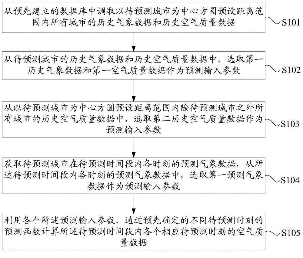
[0067] see figure 1 , figure 1 It is a flow chart of an air quality prediction method provided by an embodiment of the present invention. Such as figure 1 As shown, the method includes:

[0068] Step S101, retrieve the historical meteorological data and historical air quality data of all areas within the preset distance range centered on the area to be predicted from the pre-established database;

[0069] Specifically, the database includes historical meteorological data and historical air quality data of each region within a first preset time from the current moment. Further, the first preset time, optionally, is two months. The preset distance, optionally, is 300 kilometers.

[0070] Specifically, the meteorological data include wind speed, wind direction, temperature, pressure, atmospheric vertical instability, and the like.

[0071] Step S102, selecting the first historical meteorological data and the first air quality data from the historical meteorological data and...

Embodiment 2

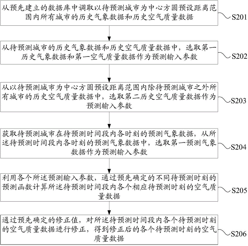
[0126] see figure 2 , figure 2 It is a flow chart of another air quality prediction method provided by an embodiment of the present invention. Such as figure 2 As shown, the method includes:

[0127] Step S201, retrieve the historical meteorological data and historical air quality data of all areas within the preset distance range centered on the area to be predicted from the pre-established database;

[0128] Specifically, the database includes historical meteorological data and historical air quality data of each region within a first preset time from the current moment. Further, the first preset time, optionally, is two months. The preset distance, optionally, is 300 kilometers.

[0129] Step S202, selecting the first historical meteorological data and the first air quality data from the historical meteorological data and historical air quality data of the area to be predicted as the forecast input parameters,

[0130] Specifically, the difference between the time ...

Embodiment 3

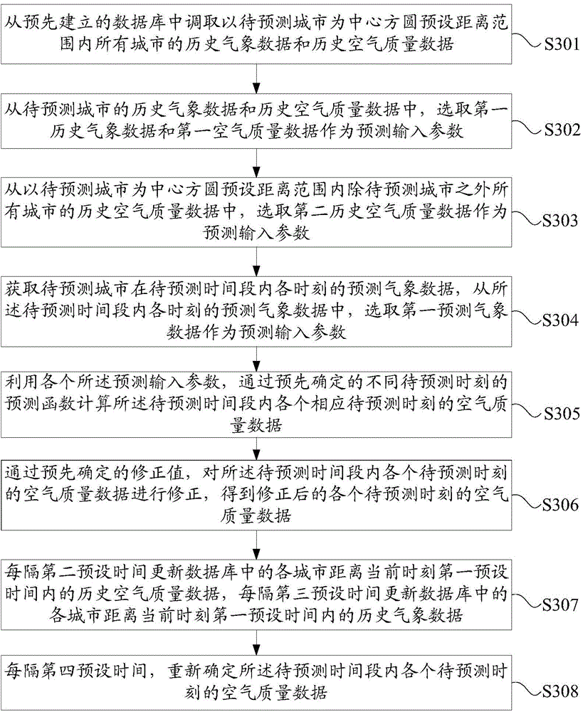
[0147] see image 3 , image 3 It is a flow chart of another air quality prediction method provided by an embodiment of the present invention. Such as image 3 As shown, the method includes:

[0148] Step S301, retrieve the historical meteorological data and historical air quality data of all areas within the preset distance range centered on the area to be predicted from the pre-established database;

[0149] Specifically, the database includes historical meteorological data and historical air quality data of each region within a first preset time from the current moment. Further, the first preset time, optionally, is two months. The preset distance, optionally, is 300 kilometers.

[0150] Step S302, selecting the first historical meteorological data and the first air quality data from the historical meteorological data and historical air quality data of the area to be predicted as the forecast input parameters,

[0151] Specifically, the difference between the time cor...


PUM


Abstract

The invention discloses an air quality prediction method and device. The method comprises the steps of calling, from a pre-established database, historical meteorological data and historical air quality data of all areas in a preset range by taking an area with air quality to be predicted as a center; selecting, from the historical meteorological data and historical air quality data of the area with the air quality to be predicted, first historical meteorological data and first air quality data as prediction input parameters, and selecting, from the historical air quality data of other areas in the preset range by taking the area with the air quality to be predicted as the center, second historical air quality data as prediction input parameters; selecting, from predicted meteorological data at each moment in a predicted time period of the area with the air quality to be predicted, first predicted meteorological data as prediction input parameters; calculating air quality data at each predicted moment through a predetermined prediction function by using all prediction input parameters. By adopting the technical scheme provided by the invention, the air quality can be more accurately predicted under the situation of limited calculation resources.

Description

technical field [0001] The invention relates to the technical field of atmospheric forecasting, in particular to a forecasting method and device for air quality. Background technique [0002] In the process of industrialization, in order to pursue rapid economic development, human beings have seriously damaged the natural environment, resulting in various pollutions, and air pollution is one of the main pollutions. Air pollution directly endangers people's health. Therefore, people have a strong need to know the air quality of a more accurate future date in order to arrange their work and life. [0003] Air quality data generally come mainly from the measured values ​​of the environmental protection department. In the current technology, there are also technologies for predicting air quality, which are divided into two types. One is to forecast based on the calculation of chemical forecasting models, that is, WRF (Weather Research and Forecasting Model, weather forecasting ...

Claims


Application Information

Patent Timeline
IPC IPC(8): G06F19/00
Inventor 刘锦龙蔡继峰潘基泽罗未萌
Owner 象辑科技股份有限公司
Learn More