Image correction method based on LED splicing display screen and image sensor

An image sensor and image correction technology, applied to static indicators, instruments, etc., can solve problems such as increased cost and uneven display effect

Inactive Publication Date: 2015-09-02
GUANGDONG VTRON TECH CO LTD
View PDF6 Cites 43 Cited by
  • Summary
  • Abstract
  • Description
  • Claims
  • Application Information

AI Technical Summary

Problems solved by technology

If the LED display unit used in the LED splicing display screen is not of the same level of LED particles, after the overall splicing, the display area corresponding to each display unit on the screen will have d

Method used


Image

  • Image correction method based on LED splicing display screen and image sensor
  • Image correction method based on LED splicing display screen and image sensor
  • Image correction method based on LED splicing display screen and image sensor

Examples


Example Embodiment

[0022] The technical solutions in the embodiments of the present invention will be clearly and completely described below with reference to the accompanying drawings of the embodiments of the present invention. Obviously, the described embodiments are only a part of the embodiments of the present invention, but not all of the embodiments. Based on the embodiments of the present invention, all other embodiments obtained by those of ordinary skill in the art without creative efforts shall fall within the protection scope of the present invention.
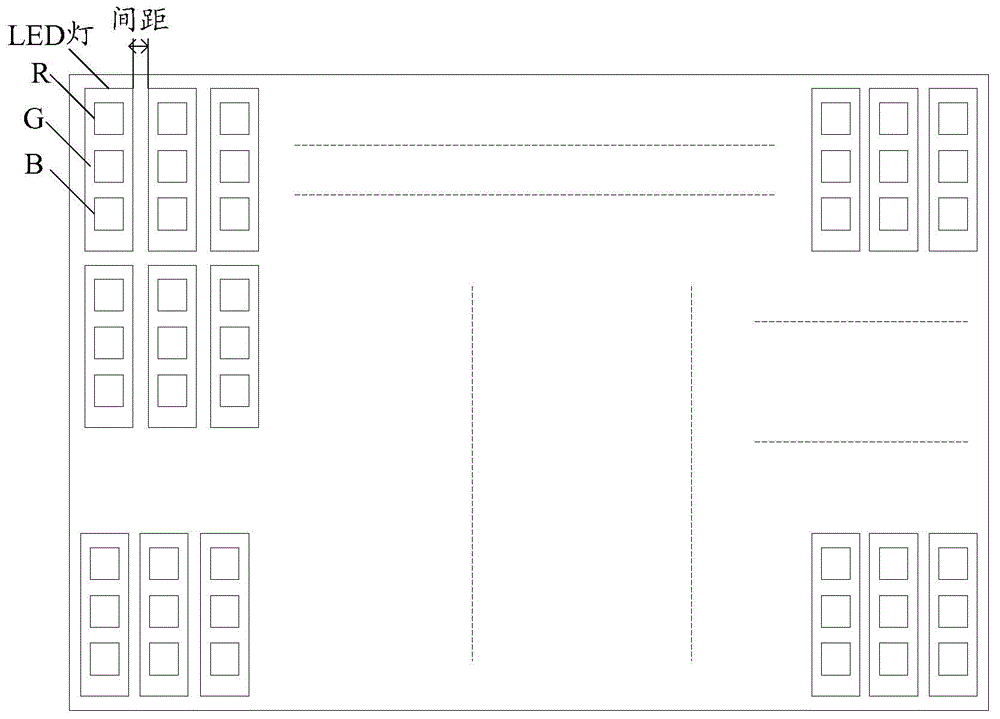
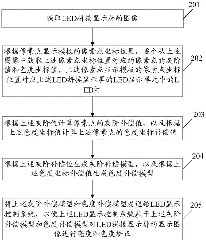
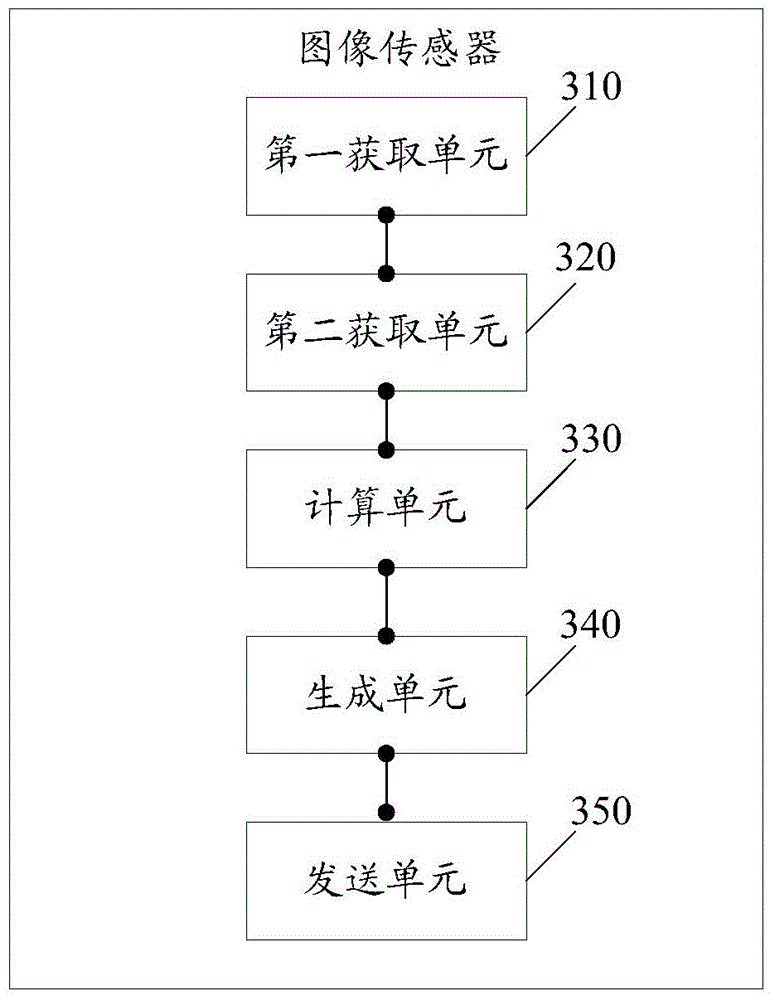
[0023] The embodiment of the present invention provides an image correction method based on an LED splicing display screen, which is used to improve the uniformity of image display and improve the display effect. The embodiment of the present invention also provides an image sensor corresponding to the image correction method based on the LED splicing display screen.

[0024] Before introducing the technical solution of the present in...


PUM


Abstract

The embodiment of the invention discloses an image correction method based on an LED splicing display screen and an image sensor. Therefore, picture display uniformity is improved and a display effect is enhanced. The method comprises: obtaining an image of an LED splicing display screen; according to a pixel point coordinate position of a pixel point display template, obtaining a gray scale value and a chromaticity coordinate value of a pixel point corresponding to the pixel point coordinate position from the image one by one; calculating a gray scale compensation value of the pixel point based on the gray scale value and calculating a chromaticity coordinate compensation value of the pixel point based on the chromaticity coordinate value; generating a gray scale compensation model based on the gray scale compensation value and generating a chromaticity compensation model based on the chromaticity coordinate compensation value; and sending the gray scale compensation model and the chromaticity compensation model to an LED display control system, thereby enabling the LED display control system to carry out brightness and chromaticity correction on a display image of the LED splicing display screen based on the gray scale compensation model and the chromaticity compensation model.

Description

technical field [0001] The invention relates to the technical field of light emitting diode (Light-emitting Diode, LED for short) splicing screen display, in particular to an image correction method and an image sensor based on an LED splicing display screen. Background technique [0002] The existing LED splicing display is composed of several LED display units using Surface Mount Device (SMD) technology. Each LED display unit includes several LED lights, and each LED light is composed of R, G and B respectively. Composed of three primary color LED particles. It can be understood that when producing LED particles, differences in process parameters or deviations in particle size cutting will affect the performance of LED particles. [0003] The performance of LED particles can be reflected from the brightness, which can be divided into different brightness levels, or can be reflected from the chromaticity, which can be divided into levels according to the color wavelength. ...

Claims


Application Information

Patent Timeline
IPC IPC(8): G09G3/32G09G3/20
Inventor 黄竑旻
Owner GUANGDONG VTRON TECH CO LTD
Why Eureka
Try Eureka