Heavy-type connector capable of realizing wiring between internal part and external part of electric shielding cabinet

An external wiring and electrical screen technology, applied in the direction of two-part connection device, connection, electrical components, etc., can solve the problems of troublesome wiring, heavy workload, and high wiring error rate, achieve convenient fixation, ensure anti-interference ability, and remove Convenient effect

Active Publication Date: 2015-09-02
CRRC QISHUYAN CO LTD
View PDF4 Cites 9 Cited by
  • Summary
  • Abstract
  • Description
  • Claims
  • Application Information

AI Technical Summary

Problems solved by technology

[0005] 1. Terminals are used for wiring. When the electrical cabinet is installed, all the wires are manually connected one by one; when the electrical cabinet is disassembled, all the wiring must be removed from the terminal. Disconnecting the wiring is very troublesome, the workload is heavy, and the wiring is wrong. higher rate;
[0006] 2. The circular connector is adopted. Since the wiring at both ends of the connector plug and socket has a bending radius requirement, the space occupied by the connector in the depth direction of the electrical cabinet is relatively large;
[0007] 3. The communication lines that directly enter the electrical cabinet need to be manually connecte

Method used


Image

  • Heavy-type connector capable of realizing wiring between internal part and external part of electric shielding cabinet
  • Heavy-type connector capable of realizing wiring between internal part and external part of electric shielding cabinet
  • Heavy-type connector capable of realizing wiring between internal part and external part of electric shielding cabinet

Examples


Embodiment Construction

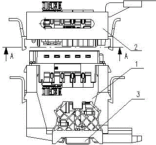
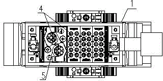
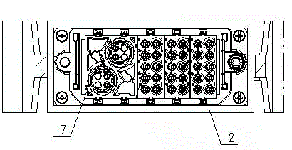
[0022] like figure 1 , 2 , 3 and 4 are schematic diagrams of the structure of the present invention, a heavy-duty connector for realizing internal and external wiring of the electrical panel cabinet, including a plug 1 and a socket 2, the plug 1 is provided with a substrate 3, and the substrate 3 is fixed in the electrical cabinet. On the guide rail, the plug 1 is provided with a male pin 4 and a male end pin sleeve 5, the male end pin sleeve 5 is provided with a pin 4, the rear end of the pin 4 is connected to the wire, and the rear end of the male end pin sleeve 5 is connected The shielding layer of the shielded wire, the socket 2 is provided with a female socket 6 and a female pin socket 7, and the female pin socket 7 is provided with a female socket 6, the rear end of the female socket 6 is connected to the wire, and the female pin socket 7. The rear end is connected to the shielding layer of the shielded wire. The plug 1 and the socket 2 are connected through the male fe...


PUM


Abstract

The invention relates to the technical field of wiring connectors, and especially relates to a heavy-type connector capable of realizing wiring between an internal part and an external part of an electric shielding cabinet. The heavy-type connector comprises a plug and a socket. The plug is provided with a substrate. The substrate is fixed on a guide rail in an electric cabinet. The plug is internally provided with a male pin and a male end pin sleeve. The male end pin sleeve is provided with the pin. The rear end of the pin is connected with an electric wire. The rear end of the male end pin sleeve is connected with a shielding layer of a shielding wire. The socket is internally provided with a female plugging sleeve and a female end pin sleeve. The female end pin sleeve is provided with a female plugging sleeve. The rear end of the female plugging sleeve is connected with the electric wire. The rear end of the female end pin sleeve is connected with the shielding layer of the shielding wire. The plug and the socket are connected through a male plugging core frame and a female plugging core frame. According to the invention, the occupied space for the installation and the wiring of the heavy-type connector is small, the heavy-type connector male end pin sleeve and the female end pin sleeve (used for the shielding wire) are capable of improving the anti-interference capability of the shielding wire, the guide rail is utilized for installation, the connector is convenient to fix, and the dismounting is convenient.

Description

technical field [0001] The invention relates to the technical field of wiring connectors, in particular to a heavy-duty connector for realizing internal and external wiring of an electrical panel cabinet. Background technique [0002] In the traditional electrical panel cabinet, the common control line adopts the terminal block to realize the electrical connection with the external electrical equipment, and the sensor signal line directly enters the electrical cabinet and is connected with the micro cabinet in the electrical cabinet. [0003] In the new type of electrical panel, the control line uses circular connectors to achieve electrical connection with external equipment, and the signal line of the sensor is connected to the micro-cabinet in the electrical panel through wire terminals. [0004] The existing electrical panel cabinets have the following problems: [0005] 1. The wiring terminal is used for wiring. When the electrical cabinet is installed, all the wires a...

Claims


Application Information

Patent Timeline
IPC IPC(8): H01R13/648H01R13/73H01R24/00
CPCH01R13/648H01R13/73H01R24/40
Inventor 夏建民吴宏军周俊
Owner CRRC QISHUYAN CO LTD
Why Eureka
Try Eureka