Predicted current control method of bidirectional DC-DC converter

A DC-DC and current prediction technology, applied in the direction of DC power input conversion to DC power output, control/regulation systems, instruments, etc., can solve problems such as output current ripple, achieve current ripple suppression, improve stability and Anti-jamming ability and effect of ensuring stability

Active Publication Date: 2018-10-09
XIAN UNIV OF TECH
View PDF2 Cites 9 Cited by
  • Summary
  • Abstract
  • Description
  • Claims
  • Application Information

AI Technical Summary

Problems solved by technology

[0005] The purpose of the present invention is to provide a bidirectional DC-DC converter predictive current control method, which can solve the obvious problem of output current ripple caused by unfixed switching frequency in the traditional predictive current control method

Method used


Image

  • Predicted current control method of bidirectional DC-DC converter
  • Predicted current control method of bidirectional DC-DC converter
  • Predicted current control method of bidirectional DC-DC converter

Examples


Embodiment Construction

[0056] The present invention will be described in detail below in conjunction with the accompanying drawings and specific embodiments.

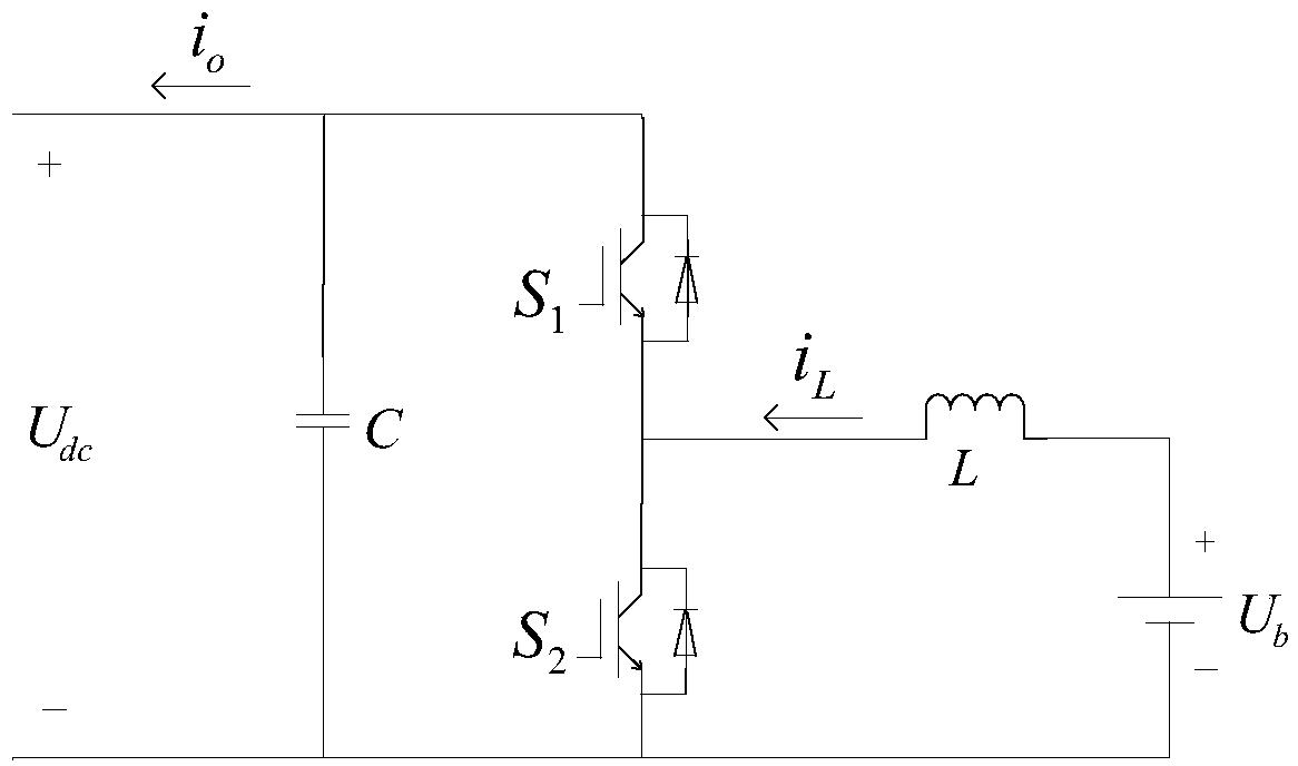
[0057] The topological diagram of the non-isolated bidirectional DC-DC converter adopted in the present invention is a bidirectional half-bridge topological structure, such as figure 1 As shown, among them, U dc and U b Represent the DC bus voltage and battery terminal voltage respectively; C is the DC bus support capacitor, L is the converter inductance; S 1 , S 2 Indicates the switching tube IGBT. The bidirectional DC-DC converter mainly has two working modes, namely Boost mode and Buck mode. When the bidirectional DC-DC converter works in Boost mode, the switch tube S 1 always off, the switch S 2 work; when the bidirectional DC-DC converter works in Buck mode, the switch tube S 1 work, switching tube S 2 Always off.

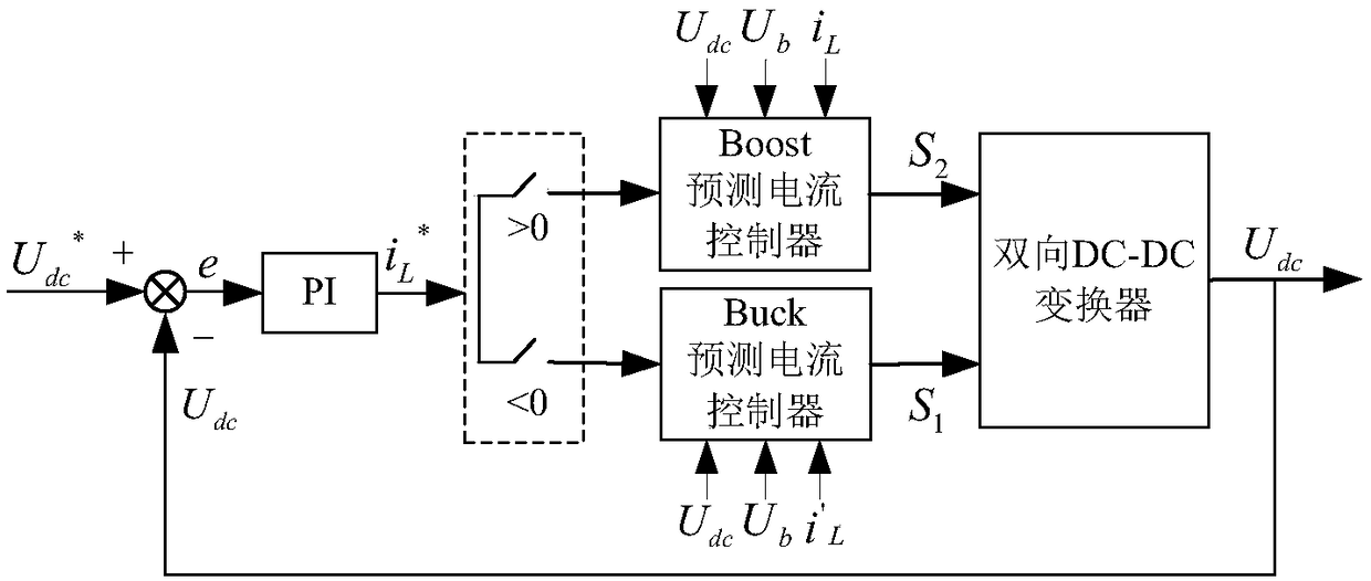
[0058] A control method for predicting the current of a bidirectional DC-DC converter according to the present inv...


PUM


Abstract

The invention discloses a predicted current control method of a bidirectional DC-DC converter. The method comprises the specific steps of obtaining a storage battery current prediction model in a discrete state through a bidirectional DC-DC converter mathematical model, calculating an on vector a action time and an off vector b action time in a Boost mode and an on vector c action time and an offvector d action time in a Buck mode of the bidirectional DC-DC converter at a time point of k+1 according to a deadbeat predicted current control theory; then designing target functions gBoost and gBuck according to action time of each vector, so as to obtain a working signal of a switch tube S2 and a working signal of a switch tube S1; and finally, allowing the working signal of the switch tube S2 and the working signal of the switch tube S1 to act on the switch tube S2 and the switch tube S1 respectively. In the traditional predicted current control method, unfixed switch frequency causes large system current ripples. The invention solves the problem in the prior art.

Description

technical field [0001] The invention belongs to the technical field of converter working mode control methods, and in particular relates to a control method for predicting current of a bidirectional DC-DC converter. Background technique [0002] Renewable energy such as solar energy, as the preferred clean energy, can effectively solve the energy and environmental problems facing the world today. However, the output power of photovoltaic power generation systems has the disadvantages of large fluctuations and the influence of external factors such as weather, which will cause DC bus voltage fluctuations. Therefore need energy storage device to work together. The bidirectional DC-DC converter is an important bridge connecting the DC bus and the energy storage medium. The charging and discharging state of the energy storage medium can be adjusted by controlling the working mode of the bidirectional DC-DC converter, so as to achieve the purpose of stabilizing the DC bus voltage...

Claims


Application Information

Patent Timeline
Patent Type & Authority Applications(China)
IPC IPC(8): H02M3/158H02M1/15H02J7/00
CPCH02J7/0071H02M1/15H02M3/1582
Inventor 杨惠晁凯悦孙向东骆姗张琦
Owner XIAN UNIV OF TECH
Why Eureka
Try Eureka