Stamping detection mechanism of stamping-welding line

A detection mechanism, stamping welding technology, applied in the direction of metal processing equipment, metal processing, manufacturing tools, etc., can solve the problems of insufficient welding length, personal injury of operators, false welding, etc., and achieve high production efficiency, low product scrap rate, The effect of stamping stability

Active Publication Date: 2015-09-09
重庆市荣昌区富民生产力促进中心有限公司
View PDF7 Cites 2 Cited by
  • Summary
  • Abstract
  • Description
  • Claims
  • Application Information

AI Technical Summary

Problems solved by technology

[0002] General stamping is produced by manual operation of metal punching machines. In manual operation, the processing accuracy is often not up to the requirements due to insufficient feeding. A slight negligence of the operator may cause personal injury. The professional technical requirements for employees are relatively high. General assembly And welding is produced by a single person and a single machine. The operator's technical level and operating specifications have a great impact on product quality. The welding length and welding quality are completely controlled by the operator's experience, so the welding length is often insufficient or too long, false welding, missing welding Such quality problems directly affect the performance and service life of the product. In view of this, it is necessary to improve the stamping detection mechanism of the existing stamping and welding production line.

Method used


Image

  • Stamping detection mechanism of stamping-welding line
  • Stamping detection mechanism of stamping-welding line
  • Stamping detection mechanism of stamping-welding line

Examples


Embodiment Construction

[0015] The preferred embodiments of the present invention will be described in detail below in conjunction with the accompanying drawings, so that the advantages and features of the invention can be more easily understood by those skilled in the art, so as to define the protection scope of the present invention more clearly.

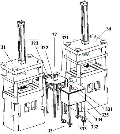
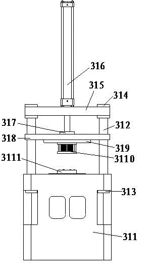
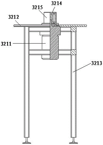
[0016] see Figure 1 to Figure 4 , the embodiment of the present invention includes:

[0017] A stamping detection mechanism of a stamping welding production line, the stamping detection mechanism of the stamping welding production line includes a punching hole device 31, a stamping transposition device 32, a stamping detection device 33 and a bending and flanging device 34 are all installed on the factory floor, the stamping The stamping transposition manipulator 323 of the transposition device 32 faces the stamping hole device 31, and the stamping transposition manipulator 323 rotates 90 degrees counterclockwise and is located under the stamping detect...


PUM


Abstract

The invention discloses a stamping detection mechanism of a stamping-welding line. The stamping detection mechanism comprises a punching device, a stamping switching device, a stamping detection device and a bending flanging device; the punching device, the stamping switching device and the bending flanging device are transversely mounted side by side on the floor in a factory; the stamping detection device is disposed in the front of the stamping switching device; the punching device comprises a base, a tie post, a lock ring, a lock disc, an upper ejector plate, a punching cylinder, a punching check disc, an upper pressure plate, an upper die mounting plate, an upper punching ide, a lower punching die and a punching base plate; the upper pressure plate is provided with the punching cylinder; a piston rod of the punching cylinder is connected with the punching check disc which is fixed to the upper pressure plate; the lower plane of the upper pressure plate is provided with the upper die mounting plate; the upper punching die is fixed to the lower plane of the upper die mounting plate; the punching check disc is fixed to the upper pressure plate; the lower plane of the upper pressure plate is provided with the upper die mounting plate; the upper punching die is fixed to the lower plane of the upper die mounting plate; the upper punching die corresponds to the lower punching die in position. The stamping detection mechanism has the advantages that stamping is stable, product scrap rate is low, and production efficiency is high.

Description

technical field [0001] The invention relates to the field of mechanical automation, in particular to a stamping detection mechanism of a stamping welding production line. Background technique [0002] General stamping is produced by manual operation of metal punching machines. In manual operation, the processing accuracy is often not up to the requirements due to insufficient feeding. A slight negligence of the operator may cause personal injury. The professional technical requirements for employees are relatively high. General assembly And welding is produced by a single person and a single machine. The operator's technical level and operating specifications have a great impact on product quality. The welding length and welding quality are completely controlled by the operator's experience, so the welding length is often insufficient or too long, false welding, missing welding Such quality problems directly affect the performance and service life of the product. In view of ...

Claims


Application Information

Patent Timeline
Patent Type & Authority Applications(China)
IPC IPC(8): B21D22/02B21C51/00
CPCB21C51/00B21D22/02
Inventor 黄掌飞
Owner 重庆市荣昌区富民生产力促进中心有限公司
Why Eureka
Try Eureka