
Large-scale high-precision gear compound grinding center

A compound grinding, high-precision technology, applied in the direction of grinding frame, grinding bed, grinding slide, etc., can solve the difficulties of workpiece lifting, clamping, calibration and detection, low equipment utilization rate, low production efficiency, etc. problems, to achieve the effect of reducing the number of machine tools and fixtures, reducing empty grinding time, and improving processing efficiency

Active Publication Date: 2017-06-16
秦川机床工具集团股份公司
View PDF5 Cites 1 Cited by
  • Summary
  • Abstract
  • Description
  • Claims
  • Application Information

AI Technical Summary

Problems solved by technology

[0003] The purpose of the present invention is to provide a large-scale high-precision gear compound grinding center to solve the problem that the current large-scale precision gears need to be processed on multiple large-scale machine tools, the auxiliary time between processes is long, the utilization rate of equipment is low, the working area is large, and the workpiece Difficulties in lifting, clamping, calibration, and detection, high processing costs, low production efficiency, and difficulty in ensuring accuracy

Method used


Image

  • Large-scale high-precision gear compound grinding center
  • Large-scale high-precision gear compound grinding center
  • Large-scale high-precision gear compound grinding center

Examples


Embodiment

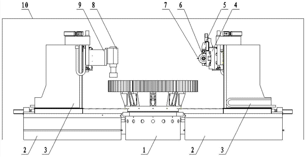
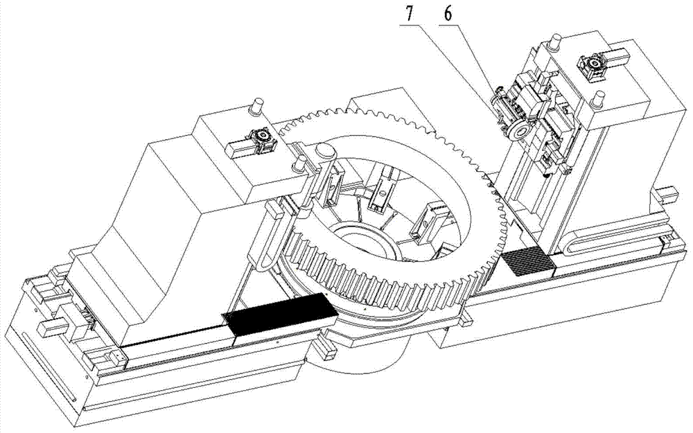
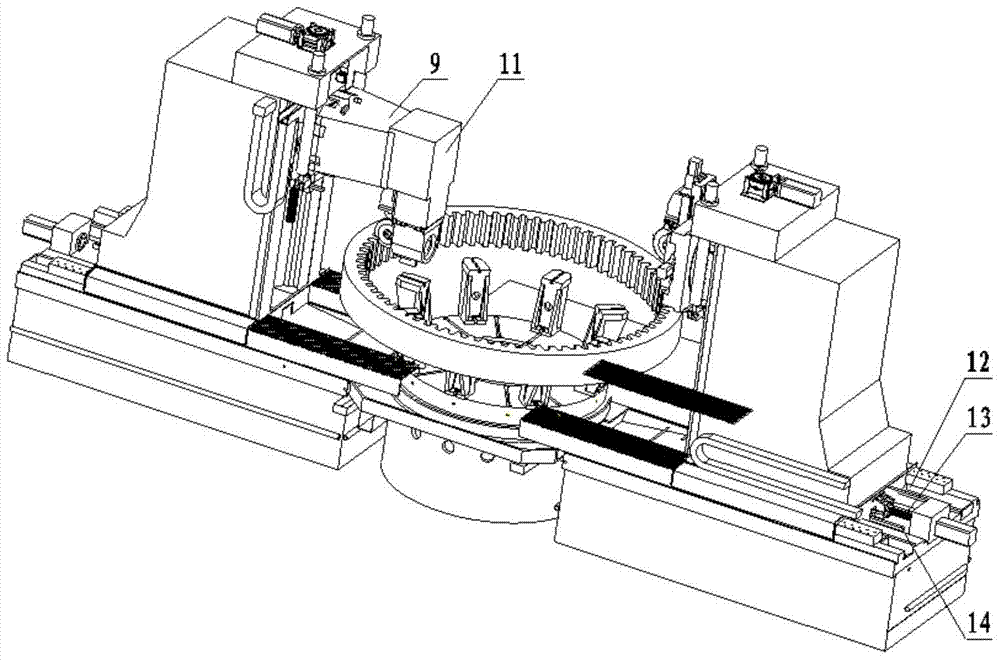
[0076] Such as Figure 1 to Figure 8 As shown, a large-scale, high-precision gear compound grinding center adopts a vertical structure and a symmetrical layout. The rotary table 1 is installed on the adjustment pad iron and connected with the foundation through anchor bolts. The external gear grinding function module is arranged on the right side of the rotary table, including bed 2, column 3, grinding wheel frame 4, grinding wheel dressing device 5, external gear grinding device 6, on-machine measuring device 7; internal gear, inner hole and The end face grinding function module is arranged on the left side of the rotary table, including bed 2, column 3, internal tooth grinding device 11, inner hole and end face grinding device 8. The large-scale, high-precision gear compound grinding center also includes an electrostatic mist absorption system 15, a grinding oil cooling and filtering system 16, and a machine tool safety system 17. This layout method has a compact structure...


PUM


Abstract

The invention provides a large-scale high-precision gear compound grinding center. The external gear grinding function module is arranged on the right side of the rotary table, including a bed, a column, a grinding wheel frame, a grinding wheel dressing device, an external gear grinding device, and on-machine measurement. Device; the internal gear, internal hole and end surface grinding functional modules are arranged on the left side of the rotary table, including the bed, column, internal hole and end surface grinding device, and internal tooth grinding device. The invention realizes one-time clamping of large gears, completes the grinding and precision detection of tooth surfaces, inner holes and end faces, and solves the difficulties of lifting, clamping, calibration and detection of large gears, as well as high processing costs, low production efficiency and difficult precision. The problem of guarantee greatly reduces the auxiliary time between processes, reduces the number of machine tools and fixtures, shortens the processing cycle, saves the operating area, significantly improves economic benefits, and completely changes the traditional processing of producing large gears with multiple large machine tools and gear gauges Way.

Description

technical field [0001] The invention belongs to the technical field of numerical control machine tools, and in particular relates to a large-scale, high-precision numerical control gear compound grinding machine tool. Background technique [0002] For emerging industries such as marine resource development equipment, large ships, high-speed locomotives, wind power, nuclear power, and aerospace that are currently being vigorously developed, large, high-precision hard-toothed gears are key power transmission components in these heavy machinery transmission industries. Large-scale, high-precision hard-tooth surface gear processing routes are mostly processed by hobbing, milling, gear shaping, etc. After the gear teeth are processed, heat treatment is performed to increase the hardness and then the tooth surface, inner hole, end surface, and internal tooth grinding are performed. , and finally perform precision testing on a large gear gauge. These processes require multiple lar...

Claims


Application Information

Patent Timeline
Patent Type & Authority Patents(China)
IPC IPC(8): B24B25/00B24B27/00B24B41/04B24B53/06B24B41/02B24B49/12B24B49/00B24B55/00B23F5/02B23F23/00
CPCB23F5/02B23F23/00B24B25/00B24B27/0023B24B27/0069B24B41/02B24B41/04B24B49/00B24B49/12B24B53/06B24B55/00
Inventor 郭召樊利军
Owner 秦川机床工具集团股份公司
Learn More