Three-claw gripping device

A technology of grabbing device and three-jaw chuck, which is applied in the direction of manipulators, collets, manufacturing tools, etc., can solve problems such as complex structure, unreliability, and manufacturing difficulties, and achieve simple manufacturing process, many objects to grab, and simplified structure Effect

Active Publication Date: 2015-09-09
HEBEI UNIV OF TECH
View PDF10 Cites 17 Cited by
  • Summary
  • Abstract
  • Description
  • Claims
  • Application Information

AI Technical Summary

Problems solved by technology

Most of the existing manipulators have two claws. When grabbing a cylinder or an ellipsoid, there are only two contacts, which is not reliable. When a three-claw hand grabs a cylinder or an ellipsoid, there are three contacts. However, the existing three-jaw manipulator has Most of the claw fingers are radial translation, which realizes the grasping of the claw fingers together. This kind of three-claw manipulator involves the radial and axial two-way movement of the claw fingers. The structure is complex, and the whole mechanism is large in size, which is not conducive to the grasping operation.
In addition, the existing mechanical claws usually adopt a pneumatic structure. Due to its complex mechanism, difficult manufacturing and poor controllability, precise opening and closing cannot be achieved. At the same time, the complex structure will also increase the cost of the manipulator, and it is easy to be damaged in practice. Do not directly affect the work efficiency of device grabbing

Method used


Image

  • Three-claw gripping device
  • Three-claw gripping device
  • Three-claw gripping device

Examples


Embodiment 1

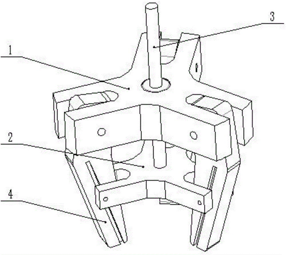
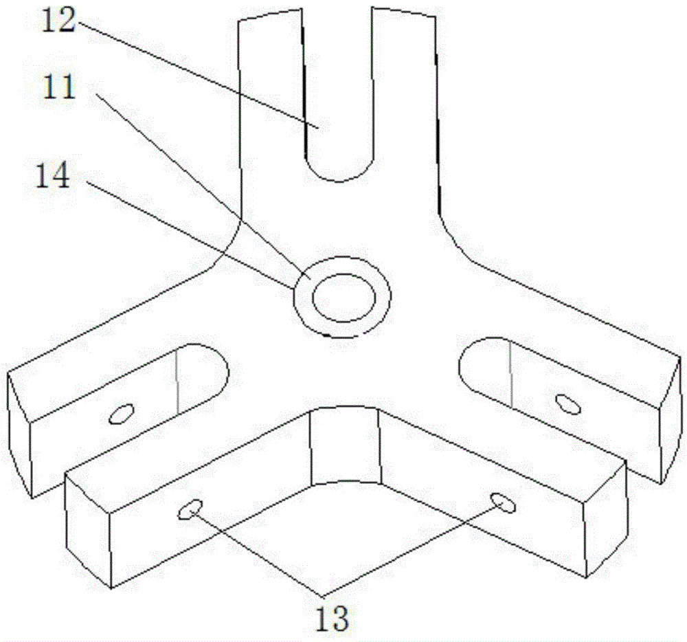
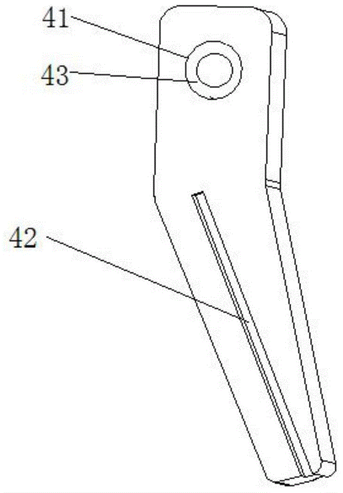
[0023] The three-jaw grasping device of the present embodiment (see Figure 4) includes a three-jaw chuck 1, a three-jaw clip 2, a telescopic rod 3 and three claw fingers 4, the upper part of the telescopic rod 3 is fixed on the three-jaw chuck 1, and the lower part is connected with the three-jaw clip 2; the upper part of the three claw fingers 4 It is fixed in the clamping groove of the three-jaw chuck 1, and the lower part of the three claw fingers 4 is fixed in the clamping groove of the three-jaw clamp 2; the three-jaw chuck is Y-shaped, and has three claws evenly distributed along the circumferential direction. The included angle between two adjacent claws is 120°. The center of the three-jaw chuck 1 is provided with a central through hole 14, and a linear bearing 11 is arranged in the center through hole. On the outer side of each claw of the three-jaw chuck 1 The clamping grooves 12 are all n-type grooves, and both sides of the n-type grooves are provided with threaded...

Embodiment 2

[0026] This embodiment adopts the connection method of Embodiment 1, and the difference is that the clamping groove on the outside of each claw of the three-jaw chuck 1 is a rectangular groove, and the volume of the three-jaw chuck 1 is that of the three-jaw clip 2. 1.5 times of the volume, the clamping groove on the outside of each claw on the three-jaw clamp 2 is also a rectangular groove, and the width of the rectangular groove on the three-jaw clamp 2 is equal to the width of the rectangular groove on the three-jaw chuck 1. The distance from the threaded through hole on the jaw chuck 1 to the central through hole of the three-jaw chuck 1 is 1.2 times the distance from the threaded through hole on both sides of the rectangular groove on the three-jaw clamp 2 to the central through hole of the three-jaw clamp 2. The thickness of 4 matches the width of the rectangular groove of three-jaw chuck 1 and three-jaw clamp 2. A layer of metallic copper is cast on the inner wall of th...

Embodiment 3

[0029] This embodiment adopts the connection method of Embodiment 1, and the difference is that the volume of the three-jaw chuck 1 is twice the volume of the three-jaw chuck 2, and the threaded through hole on the three-jaw chuck 1 is connected to the center of the three-jaw chuck 1. The hole distance is 1.3 times of the distance from the threaded through hole on both sides of the rectangular groove on the three-jaw clip 2 to the center through hole of the three-jaw clip 2. The width of the clamping groove on the three-jaw clip 2 and the three-jaw chuck 1 is different. etc., and the width of the clamping groove of the three-jaw chuck 1 matches the thickness of the upper part of the claw finger 4, the width of the clamping groove of the three-jaw clip 2 matches the thickness of the upper part of the three claw fingers 4, each finger 4 A layer of copper-plated material is provided in the through grooves at the bottom. The external drive mechanism is driven by a crank rocker.

...


PUM


Abstract

The invention relates to a three-claw gripping device which is characterized by comprising a three-claw chuck, a three-claw clip, a telescopic rod and three claw fingers, wherein the upper part of the telescopic rod is fixed on the three-claw chuck; the lower part of the telescopic rod is connected with the three-claw clip; the upper parts of the three claw fingers are fixed in clamping grooves of the three-claw clip, respectively; three claws are uniformly distributed in the circumferential direction of the three-claw chuck; an angle between two adjacent claws is 120 degrees; a central through hole is formed in the center of the three-claw chuck; a linear bearing is arranged in the central through hole; one clamping groove is arranged outside each claw of the three-claw chuck; threaded through holes are formed in two sides of each clamping groove; distances between the threaded through holes and the central through hole are equal; the three-claw clip and the three-claw chuck have the same shape structure; threads are arranged in the central through hole in the three-claw clip.

Description

technical field [0001] The invention relates to a three-claw grasping device, in particular to a grasping device for grasping cylinders or ellipsoids such as bottled beer. Background technique [0002] The gripping device can be used for gripping products in the production field. Manipulator is a very commonly used auxiliary equipment in industrial production, mainly used to grab industrial products. Most of the existing manipulators have two claws. When grabbing a cylinder or an ellipsoid, there are only two contacts, which is not reliable. When a three-claw hand grabs a cylinder or an ellipsoid, there are three contacts. However, the existing three-jaw manipulator has Most of the claw fingers move radially in translation to realize the grasping of the claw fingers together. This kind of three-claw manipulator involves the radial and axial two-way movement of the claw fingers. The structure is complex, and the entire mechanism is large in size, which is not conducive to th...

Claims


Application Information

Patent Timeline
Patent Type & Authority Applications(China)
IPC IPC(8): B25J15/10
Inventor 关玉明韩权一刘慧娟王锡瑞冀承林
Owner HEBEI UNIV OF TECH
Why Eureka
Try Eureka