Rear-mounted rubber mat assembly

A rear suspension and rubber pad technology, applied in the direction of power plant, jet propulsion device, internal combustion propulsion device, etc., can solve problems such as limited support force, tearing of rubber pad vulcanized bonding surface, rubber pad tearing, etc., to increase The effect of the ability to withstand external forces

Active Publication Date: 2015-09-09
ANHUI JIANGHUAI AUTOMOBILE GRP CORP LTD
View PDF7 Cites 3 Cited by
  • Summary
  • Abstract
  • Description
  • Claims
  • Application Information

AI Technical Summary

Problems solved by technology

The base of the rubber pad has the following defects: when the inclined steel plates 11 on both sides support the rubber pad, the supporting force they can provide is relatively limited, so the inclined steel plates 11 are easy to crack after receiving the force from the rubber pad
The above-mentioned rubber pad pressing block has the following defects: First, the interior of the rubber pad pressing block is an inverted trapezoidal hollow structure, which causes the bending point a at both ends of the rubber pad pressing block to withstand the impact force and moment of inertia of the entire power assembly. The problem of frequent cracking occurs; secondly, the inclined surfaces on both sides of the rubber pad pressing block are vulcanized and bonded together with the rubber pad. When the vehicle passes through a bad road surface, the powertrain will generate a huge instantaneous tensile force in the vertical direction and compression force, resulting in frequent tearing and fracturing of the rubber pad
The above-mentioned rubber pads have the following defects: first, the rigidity of the rubber pads is small, and the ability to resist the instantaneous impact of the powertrain of a heavy-duty dump truck is insufficient, which may easily cause the main body of the rubber pads to be fractured; second, the first slope on both sides of the rubber pads 13 and the second inclined surface 14 are directly vulcanized and bonded to the rubber pad pressing block and the rubber pad base respectively, lacking protection and positioning measures. In order to ensure the bonding strength, this structure will put forward higher requirements for the vulcanization process. Once the vulcanization process Errors in the accuracy of the rubber pad will cause frequent tearing of the vulcanized bonding surface of the rubber pad in actual use conditions

Method used


Image

  • Rear-mounted rubber mat assembly
  • Rear-mounted rubber mat assembly
  • Rear-mounted rubber mat assembly

Examples


Embodiment Construction

[0051] In order to enable those skilled in the art to better understand the technical solutions of the present invention, the present invention will be further described in detail below in conjunction with the accompanying drawings.

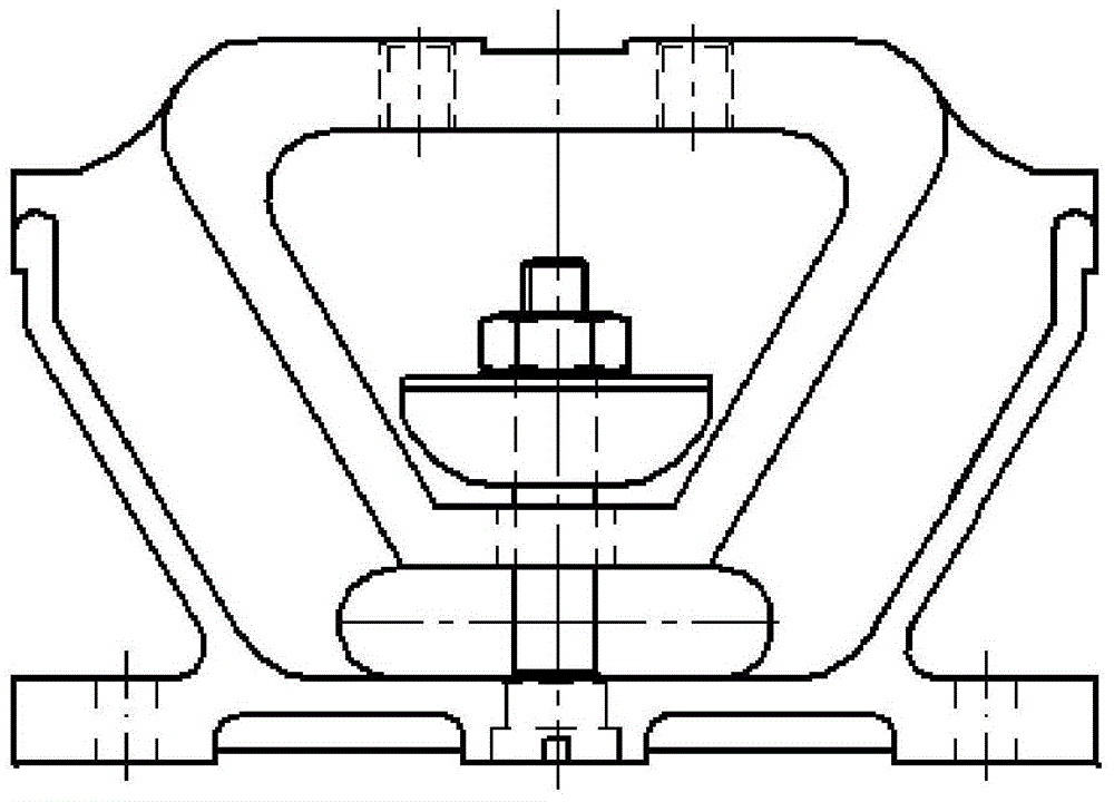
[0052] Such as Figure 4-19 As shown, the embodiment of the present invention provides a rear suspension rubber pad assembly, which includes a rubber pad base, a rubber pad pressing block and a rubber pad, wherein:

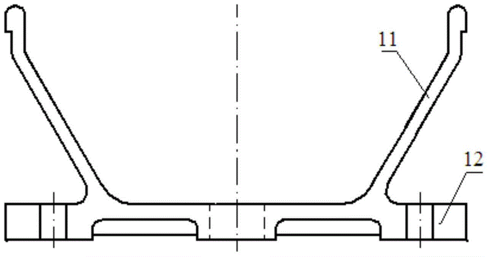
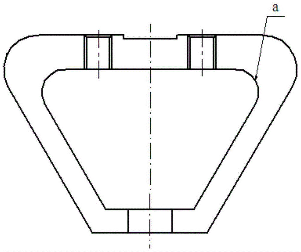
[0053] The rubber pad base is used to support the rubber pad, and it includes two half-bases fixedly connected, forming a space for supporting the rubber pad between the two half-bases. That is, after the two base halves are fixedly connected, an opening for the rubber pad to pass through and a rubber pad supporting space for finally accommodating the rubber pad can be formed between them. Above-mentioned semi-base comprises bottom plate 21, inclined support plate 22 and auxiliary support plate 23, and inclined support plate 22 is f...


PUM


Abstract

The invention discloses a rear-mounted rubber mat assembly. A rubber mat base comprises two half bases, a rubber mat supporting space is formed between the two half bases, each half base comprises a soleplate, an oblique supporting plate and an auxiliary supporting plate, one end of the auxiliary supporting plate is fixed on the soleplate, the other end of the auxiliary supporting plate is fixed on the oblique supporting plate, and a preset angle is formed between the outer wall of the auxiliary supporting plate and the oblique supporting plate; a rubber mat pressure block comprises a pressure block body with an upper installation surface and a rubber mat adhesion surface, supporting ribs are fixed inside the pressure block body, lightening holes are formed in two sides of each supporting rib, and each lightening hole is formed by encircling the inner wall of the pressure block body and the supporting rib; the rubber mat comprises two rubber mat bodies which are fixedly connected with each other, each rubber mat body comprises at least two superimposed bodies as well as a liner plate which is fixed between two adjacent bodies, and two opposite surfaces of the liner plate are respectively fit to the oblique surfaces of the two bodies. The rubber mat base and the rubber mat pressure block in the rear-mounted rubber mat assembly are unlikely to fracture, and the rubber mat is unlikely to fracture.

Description

technical field [0001] The invention relates to the technical field of automobile structures, in particular to a rear suspension rubber pad assembly. Background technique [0002] In recent years, with the rapid advancement of national urbanization, heavy-duty engineering dump trucks have been continuously developed. The weight of the powertrain of a heavy-duty dump truck is generally more than 1000kg. Under severe working conditions, the suspension part of the powertrain will be subject to a huge impact. [0003] In the current heavy-duty construction dump trucks, there are many types of rear suspension rubber pad assemblies in the powertrain, but the rear suspension rubber pad assembly mainly includes rubber pad pressing blocks, rubber pads, rubber pad bases and limit bolts, etc. structured as figure 1 shown. [0004] Such as figure 2 As shown, the traditional rubber pad base is divided into two symmetrical parts, and one side is composed of an inclined steel plate 11...

Claims


Application Information

Patent Timeline
Patent Type & Authority Applications(China)
IPC IPC(8): F16F15/08B60K5/12
CPCB60K5/1208F16F1/373F16F15/08
Inventor 董金国王俊伟高艳军李海波惠周朋许芳王立立
Owner ANHUI JIANGHUAI AUTOMOBILE GRP CORP LTD
Why Eureka
Try Eureka