Gas lubrication cluster spiral groove end face mechanical sealing structure

A kind of end face mechanical seal and mechanical seal technology, which is applied in the direction of engine seal, mechanical equipment, engine components, etc., can solve the problems of high-speed operation stability and poor sealing performance, difficulty in meeting the operation requirements of mechanical seal, and contact wear of seal end face. , to achieve the effect of strong anti-disturbance ability, large bearing capacity and enhanced compression effect

Inactive Publication Date: 2015-09-09
ZHEJIANG UNIV OF TECH
View PDF9 Cites 6 Cited by
  • Summary
  • Abstract
  • Description
  • Claims
  • Application Information

AI Technical Summary

Problems solved by technology

However, these spiral grooves and their derivative groove dry gas seals still have poor low-speed start-stop characteristics, insufficient air film stiffness during high-speed operation, and excessive leakage rates, which lead to dry gas seals being used in high-speed rotating machinery. Difficult to open quickly, high-speed operation stability and poor sealing performance, easy to produce contact wear on the sealing end face, it is difficult to meet the operation requirements of mechanical seals under high-parameter conditions such as high speed

Method used


Image

  • Gas lubrication cluster spiral groove end face mechanical sealing structure
  • Gas lubrication cluster spiral groove end face mechanical sealing structure
  • Gas lubrication cluster spiral groove end face mechanical sealing structure

Examples


Embodiment 1

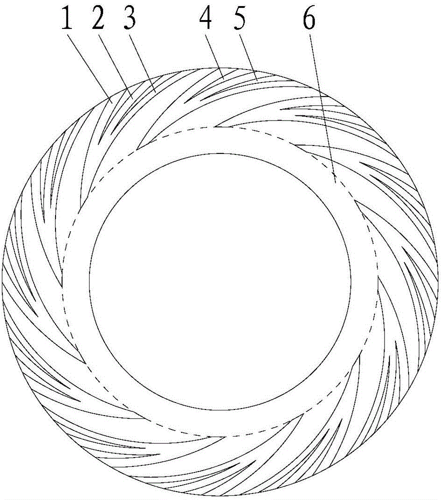
[0025] see figure 1 , 2 , a gas-lubricated cluster spiral groove end face seal structure, which includes a moving ring and a static ring of a mechanical seal, characterized in that: one side of the end faces of the moving ring and the static ring is the high-pressure side, that is, the upstream, and the moving ring and the static ring The other side of the end face of the ring is the low-pressure side, that is, the downstream side. The end face of at least one seal ring in the moving ring or the static ring is provided with a plurality of bunched spiral grooves distributed symmetrically along the circumference of the end face. The bunched spiral grooves are formed by a plurality of spiral Micro-miniature spiral grooves 1, 2 and 3 with different angles are combined along the circumferential direction of the end surface. The micro-miniature spiral grooves 1, 2 and 3 are separated by non-grooved sealing weirs 4 and 5 on the high pressure side. On one side, the groove roots are s...

Embodiment 2

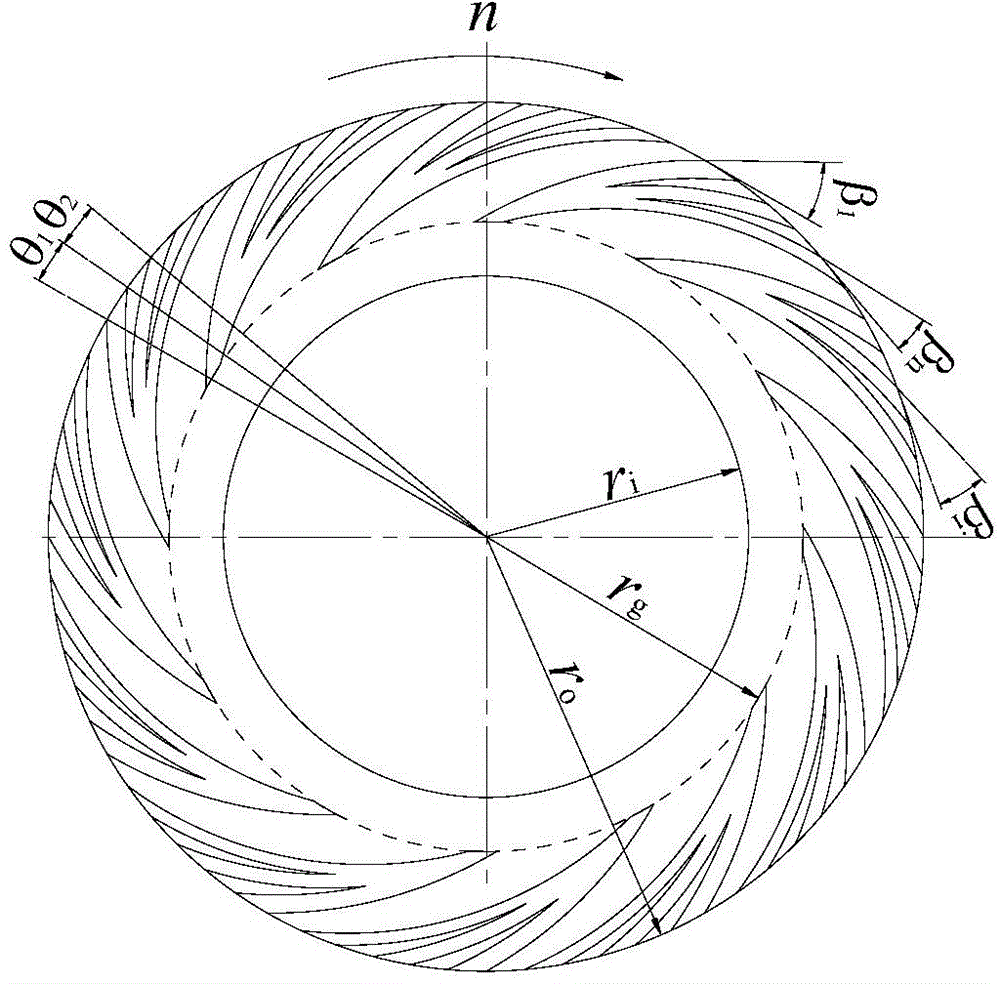
[0032] refer to image 3 , 4 , the difference between this embodiment and Embodiment 1 is that the depths of the miniature helical grooves 1, 2 and 3 in the same clustering helical groove at the same radius gradually become shallower against the rotational speed direction, that is, h 1 i n , where h n is the groove depth of the first miniature helical groove 3 against the rotational speed direction, h 1 is the groove depth of the last tiny helical groove 1 against the rotation speed direction, h i It is the groove depth of the micro-miniature spiral groove 2 in the middle, and the rest of the structures and implementations are the same as those in Embodiment 1.

Embodiment 3

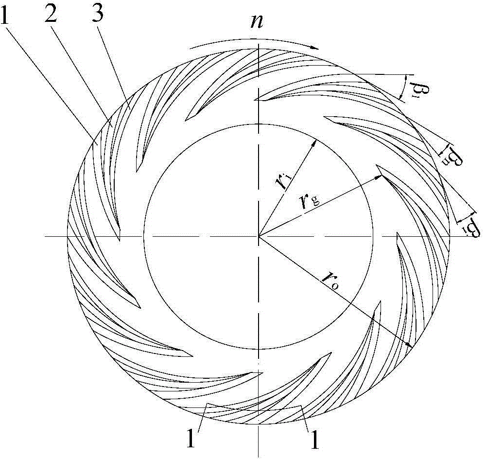
[0034] refer to Figure 5 , the difference between this embodiment and the first embodiment is that the helix angle β of the middle micro-sized helical groove 2 i and the helix angle β of the last tiny helical groove 3 along the rotational speed direction n Equal, or the helix angle β of the tiny helical groove 2 in the middle i and the helix angle β of the first tiny helical groove 1 along the rotational speed direction 1 Equal, all the other structures and implementations are the same as in Example 1.


PUM


Abstract

A gas lubrication cluster spiral groove end face mechanical sealing structure comprises a moving ring and a stationary ring of a mechanical seal. One side of the end face of the moving ring and one side of the end face of the stationary ring are high-pressure sides, namely, upper streams, and the other side of the end face of the moving ring and the other side of the end face of the stationary ring are low-pressure sides, namely, lower streams. A plurality of cluster spiral grooves symmetrically distributed along the circumference of the end face are formed in the end face of at least on sealing ring of the moving ring or the stationary ring, the cluster spiral grooves are formed by combining a plurality of micro spiral grooves with different spiral angles in the circumferential direction of the end face, the micro spiral grooves in the same cluster spiral groove are separated by a sealing weir free of grooves on the high-pressure side, the groove roots of the micro spiral grooves in the same cluster spiral groove are overlaid and communicated to a whole on the lower-pressure side, and sealing dams are arranged on the down streams of the cluster spiral grooves. Through the convergence configuration of bionic high-speed flyer wings and the alula structure of flyer wing front edges, the gas lubrication cluster spiral groove end face mechanical sealing structure has a high flow guide effect and compression function on fluid media, the low-speed start and stop characteristic, high-speed running stability and sealing performance of the seal can be improved, the high-speed disturbance rejection capacity of the seal is improved, and end face abrasion is avoided.

Description

Technical field: [0001] The present invention relates to a gas end face mechanical seal structure of a rotary fluid machine, in particular to a gas lubricated bundled spiral groove end face mechanical seal structure, which can be used for shafts of various centrifugal compressors, expanders, pumps, reaction kettles and other rotating machines end seal. Background technique: [0002] Due to its unique advantages, dry gas seals have been widely used in various medium and high-speed rotating machinery, such as centrifugal compressors, expanders, fans, etc. The dry gas seal is to open various fluid dynamic and static pressure grooves on the sealing end surface. When the moving ring rotates, the gas medium is pumped into the sealing end surface by using the dynamic and static pressure effect of the groove, and the fluid medium entering the end surface is blocked from flowing at the root of the groove. Therefore, a certain opening force is generated and the end face is pushed awa...

Claims


Application Information

Patent Timeline
Patent Type & Authority Applications(China)
IPC IPC(8): F16J15/34
CPCF16J15/34
Inventor 彭旭东江锦波白少先李纪云
Owner ZHEJIANG UNIV OF TECH
Why Eureka
Try Eureka