Fluid dynamic pressure type mechanical seal used for nuclear main pump and mechanical seal system of nuclear main pump

A technology of mechanical sealing and fluid dynamic pressure, which is applied to the components of pumping devices for elastic fluids, liquid fuel engines, mechanical equipment, etc.

Pending Publication Date: 2015-11-11
霍凤伟
View PDF13 Cites 8 Cited by
  • Summary
  • Abstract
  • Description
  • Claims
  • Application Information

AI Technical Summary

Problems solved by technology

These three-dimensional convergent dynamic pressure grooves generally have the characteristics of fine structure, high precision, and strict roughness requirements. The machinability is generally poor, and

Method used


Image

  • Fluid dynamic pressure type mechanical seal used for nuclear main pump and mechanical seal system of nuclear main pump
  • Fluid dynamic pressure type mechanical seal used for nuclear main pump and mechanical seal system of nuclear main pump
  • Fluid dynamic pressure type mechanical seal used for nuclear main pump and mechanical seal system of nuclear main pump

Examples


Example Embodiment

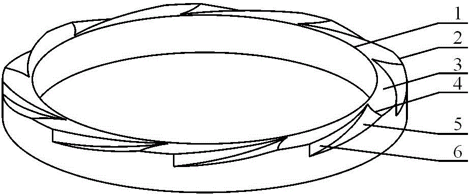
[0105] Example 1: Please refer to figure 1 , figure 2 and image 3 .

[0106] A hydrodynamic mechanical seal for a nuclear main pump, including a static ring and a moving ring. A shallow groove is provided on the sealing end face of the static ring. When working, the sealing end faces of the two rings are nearly fitted, and there is a sealing medium in the gap , the rotating shaft drives the moving ring to rotate relative to the static ring. The outer diameter side of the sealing end face is the high pressure test, that is, the upstream side, and the inner diameter side is the low pressure test, that is, the downstream side. The sealing medium leaks through the gap between the two sealing end faces. The shallow groove is a kind of Curved surface groove, the bottom surface of the curved surface groove is a curved surface. The curved surface is a single surface that the seal ring makes with respect to a circle with a radius of 175 mm and an inclination angle of 0.0002 radians...

Example Embodiment

[0109] Example 2: Please refer to Figure 4 , Figure 5 , Image 6 and Figure 7 .

[0110] The difference from Embodiment 1 lies in the different shapes of the curved grooves. Figure 4 Indicates the shape of the curved surface groove on the sealing end surface in Example 2, Figure 5 Yes Figure 4 A top view of the shape shown, Image 6 Yes Figure 4 The schematic diagram of the surface groove formation is shown, Figure 7 Yes Image 6Top view of the schematic shown. The said motion rule is that the circle inclined to the seal end face performs a composite motion consisting of a linear motion slightly inclined to the seal end face and a rotation around the axis of the seal ring. In this embodiment, the curved surface groove formed is composed of a smooth curved surface, which smoothly transitions to the sealing end surface without steep side walls, and the intersection line between the curved surface and the sealing end surface is a smooth curve, and the distance b...
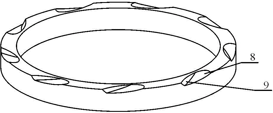
Example Embodiment

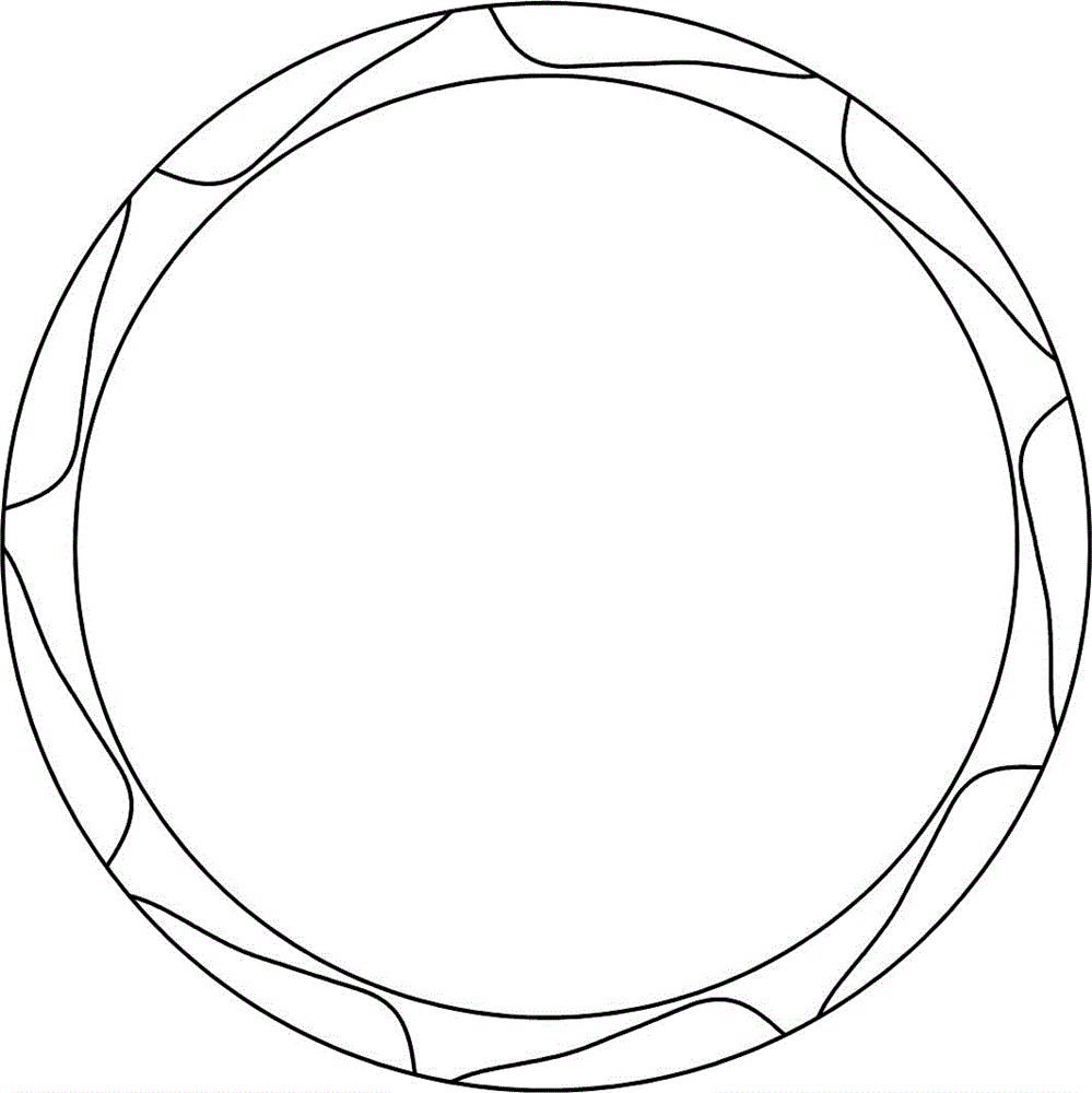
[0111] Example 3: Please refer to Figure 8 , Figure 9 and Figure 10 .

[0112] The difference from the previous embodiments lies in the different shapes of the curved grooves. Figure 8 Indicates the shape of the curved surface groove on the sealing end surface in Example 3, Figure 9 Yes Figure 8 A top view of the shape shown, Figure 10 Yes Figure 8 Schematic diagram of surface groove formation shown. The motion rule is a composite motion composed of a rotation with a straight line parallel to the sealing end surface as an axis and a rotation around the axis of the seal ring. In this embodiment, the intersection line between the curved surface groove and the sealing end surface is a smooth curve, and the curved surface groove is generally symmetrical with respect to the radial line of the seal ring, and can generate enough pressure when the pump shaft rotates forward or reverse. fluid dynamic effect.


PUM

PropertyMeasurementUnit
Radiusaaaaaaaaaa

Abstract

The invention relates to a fluid dynamic pressure type mechanical seal used for a nuclear main pump and a mechanical seal system, comprising the mechanical seal, of the nuclear main pump. The fluid dynamic pressure type mechanical seal used for the nuclear main pump is characterized in that shallow grooves with cambered surfaces as bottom faces are formed in the sealing end face of a movable ring or a fixed ring; the cambered surfaces are part of a smooth and continuous cambered surface formed by the movement trail when a circumference moves according to the motion law in a three-dimensional space; and the cambered surface grooves each have a three-dimensional convergence shape which is gradually shallowed and narrowed from the high-pressure side to the low-pressure side and have a stronger convergence characteristic. Each cambered surface groove can be accurately formed through a grinding method; and the machining accuracy is high. Compared with an ordinary fluid dynamic pressure type mechanical seal used for the nuclear main pump, the fluid dynamic pressure effect is stronger, the fluid film rigidity is higher, stability and reliability are higher, and the service life is longer. Compared with the ordinary mechanical seal system for the nuclear main pump, safety is higher, and the stable running time is longer.

Description

technical field [0001] The invention belongs to the field of mechanical seals for nuclear main pumps, and relates to a hydrodynamic mechanical seal for nuclear main pumps and a mechanical seal system for nuclear main pumps, in particular to a nuclear main pump with grooves on the outside of the sealing end surface. A hydrodynamic mechanical seal with a shallow groove on a curved surface and a nuclear main pump mechanical seal system including the mechanical seal. Background technique [0002] The role of the mechanical seal for the nuclear main pump is to control the leakage of radioactive reactor coolant along the nuclear main pump shaft. It is one of the core components of the nuclear main pump, and its performance largely determines whether the nuclear power plant can last for a long time. Safe and reliable operation. The flow rate of the nuclear main pump is as high as 24,000 cubic meters per hour, the power of the driving motor is about 6,500 kilowatts, the speed is ab...

Claims


Application Information

Patent Timeline
IPC IPC(8): F04D29/12
Inventor 霍凤伟
Owner 霍凤伟
Why Eureka
Try Eureka