A multi-system flooded evaporator

A flooded evaporator and multi-system technology, applied in the field of multi-system flooded evaporators, can solve the problems of refrigerant waste, increased use costs, and difficulty in independent operation, etc., to achieve uniform heat exchange, flexible use, and improved The effect of the cooling effect

Active Publication Date: 2017-08-11
TAIZHOU LONGJIANG CHEM MACHINERY TECH
View PDF1 Cites 0 Cited by
  • Summary
  • Abstract
  • Description
  • Claims
  • Application Information

AI Technical Summary

Problems solved by technology

[0003] For example, the Chinese utility model patent application (application number: 201310016558.4) discloses a flooded evaporator and a water-cooled air-conditioning unit having the evaporator. The heat pipe support plate is arranged equidistantly perpendicular to the length direction of the shell; the partition plate is arranged in each section divided by the heat exchange tube support plate along the length direction of the shell, so that each section forms At least two partitions, the partition plate divides the inner cavity of the shell into partitions, but each partition only makes the refrigerant more stable, and it is difficult to work independently, and when the amount of refrigerant is small, the refrigerant The refrigerant enters the heat exchange tube from a water inlet, and it is difficult for the brine to fill the entire heat exchange tube or all the heat exchange tubes, but the refrigerant still needs to fill the shell and submerge all the heat exchange tubes, resulting in waste of refrigerant and increased use costs

Method used


Image

  • A multi-system flooded evaporator
  • A multi-system flooded evaporator
  • A multi-system flooded evaporator

Examples


Embodiment 1

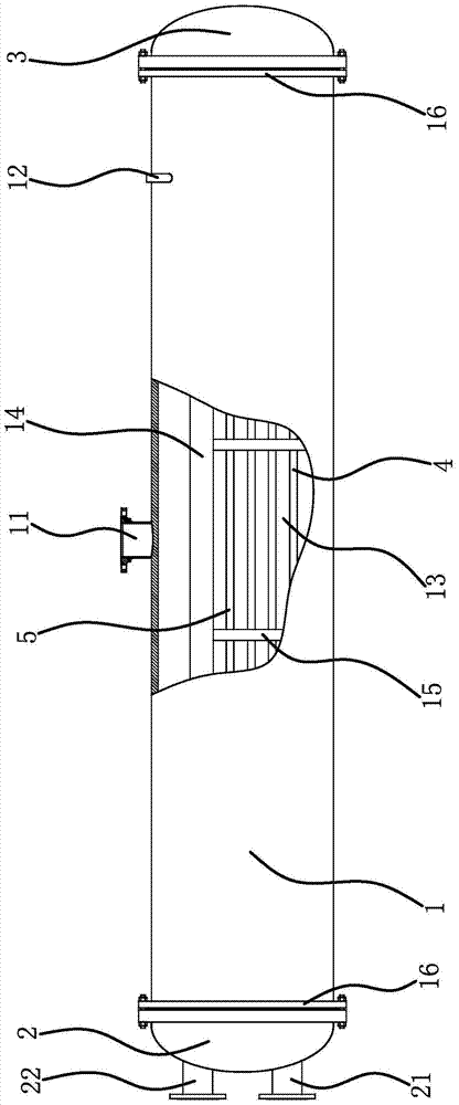
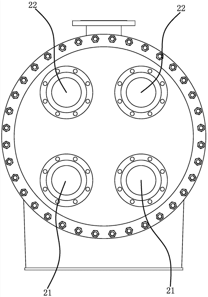
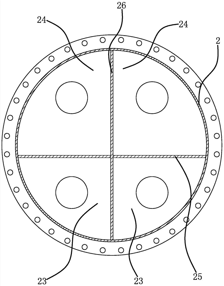
[0033] like figure 1 , figure 2 , image 3 As shown, a multi-system flooded evaporator includes a cylinder body 1, a front pipe box 2 and a rear pipe box 3, the front pipe box 2 and the rear pipe box 3 are fixedly connected to both ends of the cylinder body 1 respectively, and the cylinder body 1 is provided with a steam outlet 11 and two liquid inlets 12. The multi-system flooded evaporator also includes two groups of refrigeration circuits, each group of refrigeration circuits includes a water inlet pipe 21 and a water inlet located in the front tube box 2. Chamber 23 and water outlet chamber 24, refrigeration chamber 13 located in cylinder body 1, return chamber 31 located in rear tube box 3, several incoming heat exchange tubes 4 and several return flow heat exchange pipes 5 are fixedly connected in the refrigeration chamber 13 , the water inlet pipe 21 is connected with the water inlet chamber 23, the water outlet pipe 22 is connected with the water outlet chamber 24, ...

Embodiment 2

[0037] The structure of this multi-system flooded evaporator is basically the same as that of Embodiment 1, the difference is that Image 6 , Figure 7 , Figure 8 , Figure 9 As shown, there are three groups of refrigeration circuits, two front longitudinal partitions 26, the water inlet chamber 23 and the water outlet chamber 24 are located between the front longitudinal partition 26 and the inner wall of the cylinder 1 and between two adjacent front longitudinal partitions 26, and the shell side There are two partitions 14, the cooling chamber 13 is located between the shell-side partition 14 and the inner wall of the cylinder 1 and between two adjacent shell-side partitions 14, there are three liquid inlets 12, and the three liquid inlets 12 are connected with The three refrigeration chambers 13 correspond one to one. There are two rear longitudinal diaphragms 32, and the return cavity 31 is located between the rear longitudinal diaphragm 32 and the inner wall of the cy...


PUM


Abstract

The invention provides a multi-system flooded evaporator and belongs to the technical field of water chilling units. The multi-system flooded evaporator is used for solving the problems of refrigerant waste and use cost increase of the existing flooded evaporator. The multi-system flooded evaporator comprises a barrel, a front channel, a rear channel and at least two refrigerating circuits; each refrigerating circuit comprises a water inlet pipe, a water inlet cavity, a water outlet cavity, a refrigerating cavity and a reflux cavity; the water inlet pipe is communicated with the water inlet cavity; the water outlet pipe is communicated with the water outlet cavity; one ends of a plurality of inflow heat exchange tubes and one ends of a plurality of reflux cavities all are communicated with the reflux cavity; the other ends of the inflow heat exchange tubes all are communicated with the water inlet cavity; the other end of the plurality of reflux heat exchange tubes all are communicated with the water outlet cavity. A plurality of systems in the multi-system flooded evaporator are capable of running independently or running simultaneously; as a result, the multi-system flooded evaporator is more flexible to use and lower in use cost.

Description

technical field [0001] The invention belongs to the technical field of water chillers and relates to a multi-system flooded evaporator. Background technique [0002] The flooded evaporator has gradually become a hot spot in the technical field of large-scale chillers in China. The flooded shell-and-tube evaporator is that the refrigerant flows outside the heat exchange tube, the refrigerant flows in the heat exchange tube, and the refrigerant absorbs the heat of the refrigerant For evaporation, a unit with multiple refrigeration compressors connected in parallel, the flooded evaporator is a whole. In the prior art, the pipe box structure of the multi-system flooded evaporator is designed as a single system, that is, there is only one water inlet pipe and one The outlet pipe and the shell side of the evaporator also have only one cavity, that is, the maximum heat transfer efficiency of the evaporator can only be achieved when the refrigerant outside the heat exchange tube is ...

Claims


Application Information

Patent Timeline
Patent Type & Authority Patents(China)
IPC IPC(8): F25B39/02
CPCF25B39/02
Inventor 熊从贵林文贤
Owner TAIZHOU LONGJIANG CHEM MACHINERY TECH
Why Eureka
Try Eureka