Hole filling method by blasting

A technology of explosion method and detonation method, which is applied in the field of blasting, can solve the problems of limited improvement of water hole plugging effect, limited effect of increase, and limited length of the device, so as to improve the effect of single-hole blasting, increase the amount of charge, reduce The effect of plugging length

Active Publication Date: 2015-09-09
UNIV OF SCI & TECH OF CHINA +1
View PDF11 Cites 4 Cited by
  • Summary
  • Abstract
  • Description
  • Claims
  • Application Information

AI Technical Summary

Problems solved by technology

The above methods mainly rely on increasing the friction between the newly added device and the hole wall to improve the plugging effect. Not only the cost is high, but the length of the device is limited, and the effect of the increase is also limited.
This method also does not utilize a longer plugging section, and the plugging effect of the water hole is limited.

Method used


Image

  • Hole filling method by blasting
  • Hole filling method by blasting

Examples


Embodiment 1

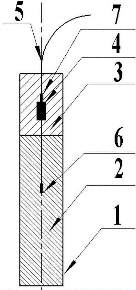
[0018] Such as figure 1 As shown, blasthole 1 is a dry hole with a diameter of 90mm and a depth of 8.0m. The charge 2 at the bottom of the blast hole uses powdered ammonium nitrate explosive, coupled with the charge. The plugging section 3 uses a mixture of rock, soil and sand. According to the conventional plugging method, the plugging length of the plugging section 3 is 4.0m, and the charging length of the charging section 2 is 4.0m. After using the explosion method to plug the hole, the plugging length can be reduced to 2.0m, and the charge length is 6.0m. Blocking charge pack 4 uses a roll of 32mm, 150g emulsion explosive. The distance between the center of the plugging cartridge 4 and the orifice is 1.3m, that is, it is located at the lower part of the middle part of the plugging section. Charge section 2 and plugging charge package 4 are detonated by electric delay detonators 6 and 7 respectively, and the sections of detonators 6 and 7 are respectively MS5 (110ms) and...

Embodiment 2

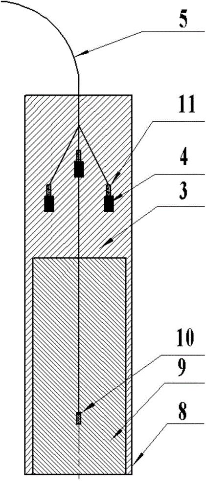
[0021] Such as figure 2 As shown, the blasthole 8 is a water hole with a diameter of Φ135mm and a depth of 15.0m. The charge 9 at the bottom of the blast hole uses a strip-packed emulsion explosive with a diameter of Φ110mm and a weight of 4kg, which is not coupled to the charge. The plugging section 3 uses a mixture of rock, soil and sand. According to the conventional plugging method, the plugging length of the plugging section 3 should be 6.0m. Due to the existence of water, it is difficult for the plugging section to achieve the plugging effect in the dry hole. The charge length of charge section 9 is 9.0m. When using the explosion method to plug holes, set 3 plugging charges 4 in the packing section, all of which use Φ32mmΦ150g emulsified explosives, the plugging length is 3.0m, and the 3 plugging charges are as follows: figure 2 The layout is 1.5m, 2.3m, and 2.3m from the orifice in the vertical direction, and the two blocking charges below are symmetrically distribu...


PUM


Abstract

The invention relates to a hole filling method by blasting. The materials used comprises two parts, i.e., a hole filling material and hole filling cartridge bags. A blast hole is sealed by using a common hole filling material; the hole filling cartridge bags are alternately arranged inside the hole filling material along the direction of the blast hole. A time-delayed detonating method is employed for allowing the cartridge bags to be detonated firstly inside the blast hole. The energy generated by the explosion of the explosive inside the hole filling cartridge bags allows the common hole filling material above and below the explosive to be compacted, thereby increasing the frictional force between the hole filling material and the wall surface of the blast hole. Meanwhile, the delayed time between a hole filling cartridge bag and a main charge of a charge section is designed, thereby achieving that the detonation gas generated by the hole filling cartridge bags inside the filling section is not escaped upon detonating the main charge, and accordingly generating a high pressure environment inside the filling section, and increasing the hole filling effect.

Description

technical field [0001] The invention belongs to the technical field of blasting, and in particular relates to a dynamic plugging method for blastholes. Background technique [0002] In the blasting operation, the blast hole needs to be blocked after the blast hole is filled with explosives, referred to as "plugging hole". The plugging quality directly determines the blasting effect. Poor plugging quality often leads to problems of punching and high block rate, and even serious consequences of flying stones hurting people. The main reasons for poor plugging quality are as follows: (1) insufficient plugging length; (2) improper selection of plugging objects or too loose; (3) water in the blast hole (ie, water hole). In order to ensure the quality of plugging, in addition to the reasonable selection of plugging materials, other commonly used methods include: (1) Increase the length of packing: increasing the length of packing can effectively improve the quality of hole pluggi...

Claims


Application Information

Patent Timeline
Patent Type & Authority Applications(China)
IPC IPC(8): F42D1/18
Inventor 马宏昊王飞沈兆武李战军崔晓荣林谋金崔宇
Owner UNIV OF SCI & TECH OF CHINA
Why Eureka
Try Eureka