
Cylinder forced centering observation pillar and embedment method thereof

A technology of forced centering and observation of piers, which is applied in the directions of measuring devices, surveying instruments, surveying and navigation, etc., can solve the problems of poor quality of standard-making construction, difficulty in accurate centering, and poor aiming eccentricity, so as to save pier bodies Concrete material, reduce the centering error, and eliminate the effect of aiming eccentricity difference

Active Publication Date: 2015-09-09
CHINA GEZHOUBA GROUP CO LTD
View PDF5 Cites 7 Cited by
  • Summary
  • Abstract
  • Description
  • Claims
  • Application Information

AI Technical Summary

Problems solved by technology

[0003] When observing these piers, a prominent problem is often encountered, that is, the eccentricity of the aiming. Sometimes due to the poor quality of the construction of the landmarks, the center of the piers is not the center of the mandatory bids, and when the sun shines on these landmarks There are refracted shadows at different angles at different times during the pier. Even if the target plate is concentric with the pier, it is difficult to accurately center it. Therefore, it is necessary to manually erect a target plate or a sign post for accurate rear-sight orientation and direction inspection.
There are two inconveniences in fixing the target plate and sign post on the center of the mark. One is that it needs to be removed when setting up the instrument for observation. The other is that the target plate and sign post are more expensive and easy to be taken away by others. Therefore, it is necessary to send people often during operations. Check and maintain, bring trouble to use

Method used


Image

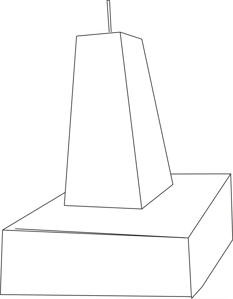
  • Cylinder forced centering observation pillar and embedment method thereof
  • Cylinder forced centering observation pillar and embedment method thereof
  • Cylinder forced centering observation pillar and embedment method thereof

Examples


Embodiment Construction

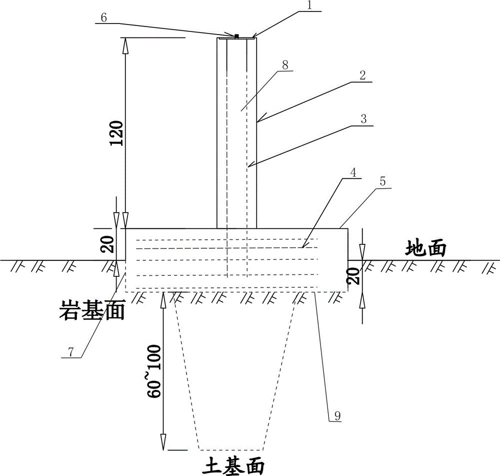
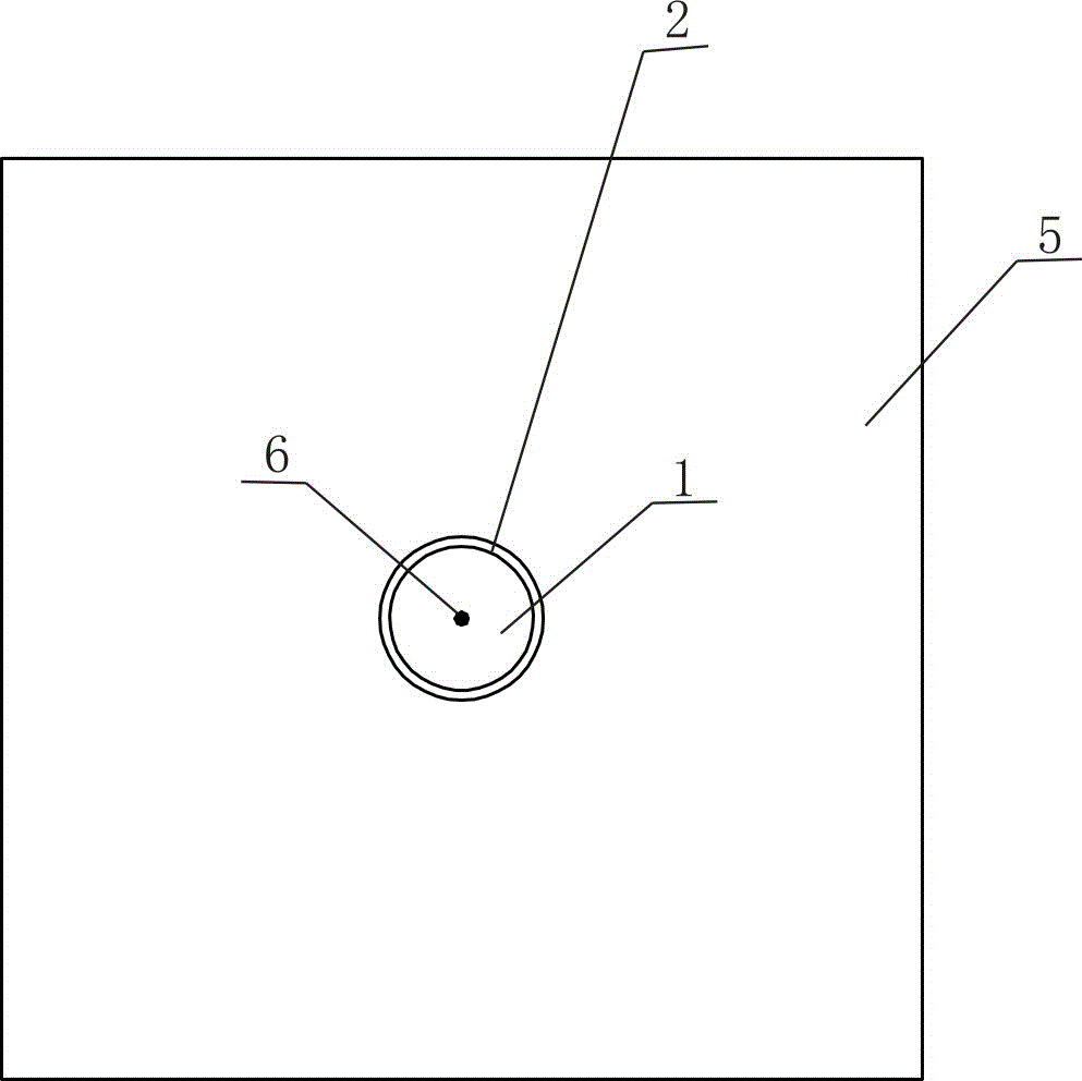
[0031] Such as figure 2 and image 3 As shown, a cylindrical forced centering observation pier,

[0032] It includes a cylindrical pipe body 2 as a pouring template, the lower part of the cylindrical pipe body 2 is wrapped with a concrete chassis 5 integrated with the cylindrical pipe body 2, and the lower part of the concrete chassis 5 is buried in the pile hole 7 under the ground surface Inside;

[0033] The height of the concrete chassis 5 above the ground is 20cm, and the height buried in the ground is 20cm;

[0034] The upper part of the cylindrical pipe body 2 is located on the concrete chassis 5 on the ground surface, and the upper concrete column 8 integrated with the cylindrical pipe body 2 is poured in the cylindrical pipe body 2, and the upper concrete column 8 is connected with the concrete chassis 5. as one;

[0035] The center of the top surface of the upper coagulation column 8 in the cylindrical pipe body 2 is fixedly provided with a forced centering dial ...


PUM


Abstract

The invention relates to a cylinder forced centering observation pillar, which comprises a cylindrical pipe adopted as a casting template, wherein a concrete chassis integrally combined with the cylindrical pipe is wrapped on the lower portion of the cylindrical pipe, the upper portion of the cylindrical pipe is positioned on the concrete chassis on the ground surface, an upper concrete column integrally combined with the cylindrical pipe is casted in the cylindrical pipe, and a forced centering scale disk is fixedly arranged on the top surface center of the upper concrete column in the cylindrical pipe. The cylinder forced centering observation pillar embedment method comprises: 1) digging a pile hole; 2) paving foundation reinforcing steel bars, and inserting four pillar vertical ribs; 3) penetrating the cylindrical pipe through the pillar vertical ribs; 4) carrying out one-time integrated casting; and 5) casting the processed forced centering scale disk so as to complete the cylinder forced centering observation pillar embedment. With the cylinder forced centering observation pillar and the cylinder forced centering observation pillar embedment method of the present invention, the construction process is simple, the sighting eccentric influence can be eliminated, and the use effect is good.

Description

technical field [0001] The invention relates to an observation pier for precision engineering measurement and an embedding method thereof, in particular to a cylinder forced centering observation pier and an embedding method thereof. Background technique [0002] At present, the high-level control network points in the field of water conservancy and hydropower construction survey in my country generally use reinforced concrete marking piers, most of which are stainless steel, and the center of the marking is forced to center, which needs to be used with connecting bolts. In the field of highway and railway construction, due to the long lines and the high cost of traditional compulsory centering pier, landmarks are often used. This brings inconvenience to the encryption and use of the control network, and also increases the instrument alignment error during the observation process. The standard pier shapes of the above-mentioned control network points mainly include square ...

Claims


Application Information

Patent Timeline
IPC IPC(8): G01C15/08
CPCG01C15/04
Inventor 邱章云田学芝
Owner CHINA GEZHOUBA GROUP CO LTD
Learn More