Composite cutter path generation method based on discrete cutter location point

A tool path and path generation technology, applied in the direction of electrical program control, digital control, etc., can solve the problems of reduced cutting speed, unstable cutting motion, and non-continuous tool path

Inactive Publication Date: 2015-09-09
柳州宏开汽车科技有限公司
View PDF5 Cites 22 Cited by
  • Summary
  • Abstract
  • Description
  • Claims
  • Application Information

AI Technical Summary

Problems solved by technology

The tool path generated by this linear interpolation method is a broken line tool path. This kind of broken line tool path often has some shortcomings in high-performance NC machining of free curves and surfaces. For example, the existence of a large number of tool p

Method used


Image

  • Composite cutter path generation method based on discrete cutter location point
  • Composite cutter path generation method based on discrete cutter location point
  • Composite cutter path generation method based on discrete cutter location point

Examples


Embodiment Construction

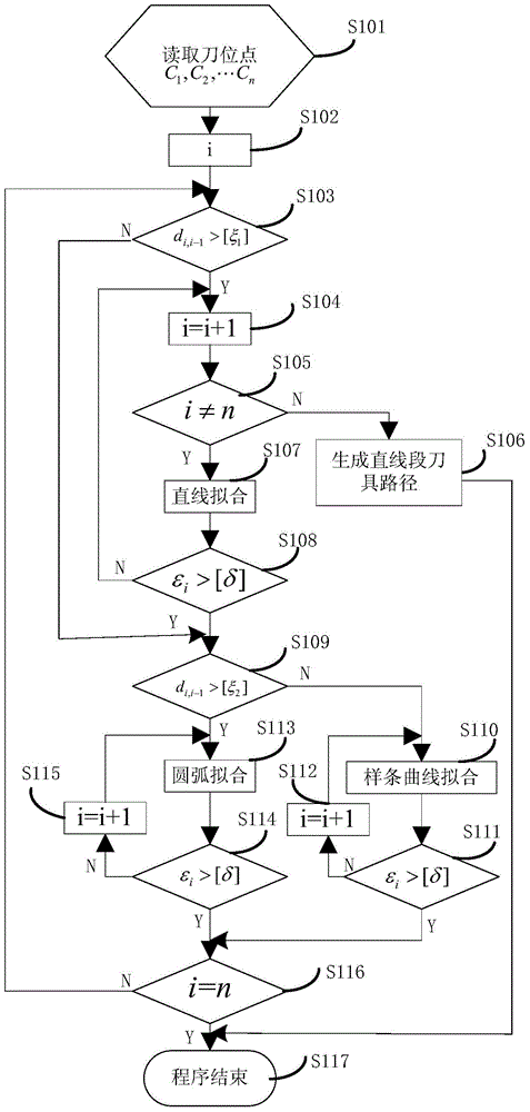
[0043] In order to make the present invention clearer, the present invention will be described in detail below in conjunction with the accompanying drawings.

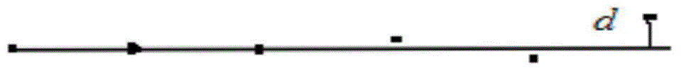
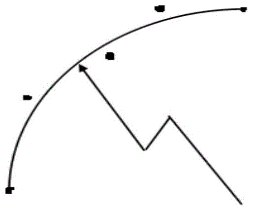
[0044] The applicant of the present invention considers that different interpolation methods have their own characteristics, for example, the linear interpolation method is easy to calculate and widely used. When the CNC (Computerized numerical control, computer numerical control) system processes high-precision curves and surfaces through linear interpolation, it uses high-density discrete tool points to represent its tool path. When the surface contour of the part is complex and the curvature of the curve changes greatly , will require more tool points, leading to the expansion of the NC program and the extension of execution time, and the smoothness of the tool path is not high. Compared with linear interpolation, quadratic interpolation such as circular arc, parabola, ellipse, and hyperbola is more accurate, and cir...


PUM


Abstract

The invention provides a composite cutter path generation method based on a discrete cutter location point. A composite cutter path is a cutter patch which comprises multiple interpolation modes such as a line, an arc, a spline curve and the like and optimization combinations thereof. The combination form changes with the shape characteristics of a processed workpiece and a processing trajectory. According to the invention, for cutter location point information on an already known processing trajectory, the composite cutter path formed by reasonable combination of the three interpolation modes as the line, the arc and the B spline curve is studied through such means as interpolation priority arrangement, error analysis, optimization segmentation, fitting calculation and the like, under the condition that allowed processing errors are satisfied, smoothing processing on the cutter path is realized, at the same time, a numerical control program is simplified, and the processing quality and efficiency are improved.

Description

technical field [0001] The invention relates to the field of curve processing, in particular to a compound tool path generation technology. Background technique [0002] In the fields of automobiles and aviation, some special transition curves and surfaces that play a role in aesthetic decoration or rigidity enhancement are often involved, which are usually also called free curve surfaces. [0003] The processing of free curves and surfaces is mainly completed by CNC milling. The quality of tool path design directly affects the surface processing quality of curves and surfaces. [0004] The tool path design of the free curve surface is usually realized by using CAM (Computer Aided Manufacturing, computer-aided manufacturing) software. In the process of tool path design for free curved surfaces, the CAM software system first calculates the tool contacts on the machined surface according to the processing conditions, and then converts them into corresponding tool points accor...

Claims


Application Information

Patent Timeline
IPC IPC(8): G05B19/19
CPCG05B19/19
Inventor 杨钦文黄莉
Owner 柳州宏开汽车科技有限公司
Why Eureka
Try Eureka