Method for Locating Oscillating Sources of Plant-Level Control Loops in Process Industry

A control loop, process industry technology, applied in general control systems, control/regulation systems, testing/monitoring control systems, etc., can solve the problem of low detection accuracy, achieve the effect of improving accuracy and eliminating serious harm

Active Publication Date: 2017-05-24
SOUTHEAST UNIV
View PDF3 Cites 0 Cited by
  • Summary
  • Abstract
  • Description
  • Claims
  • Application Information

AI Technical Summary

Problems solved by technology

[0005] Purpose of the invention: To provide a method for locating the oscillation source of the plant-level control loop in the process industry to solve the problem of low detection accuracy in the prior art and to achieve effective positioning of the oscillation source of the plant-level control loop

Method used


Image

  • Method for Locating Oscillating Sources of Plant-Level Control Loops in Process Industry
  • Method for Locating Oscillating Sources of Plant-Level Control Loops in Process Industry
  • Method for Locating Oscillating Sources of Plant-Level Control Loops in Process Industry

Examples


Embodiment Construction

[0015] The present invention is described in conjunction with the accompanying drawings. The basic principle of the present invention for positioning the oscillation source of the process industry plant-level control loop is as follows:

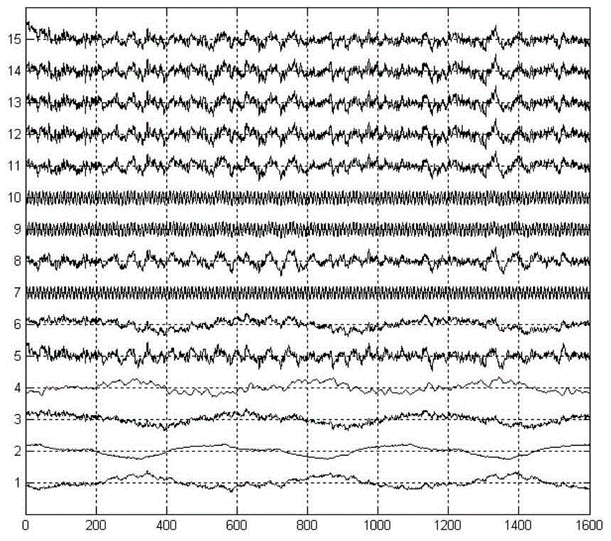
[0016] First, assume that in a multi-loop control system with N loops, multi-loop oscillation occurs. That is to say, there are M loops where loop signal oscillation occurs. Obviously, M≤N. An original loop variable data set A that only includes the above M loop signal oscillations is constructed. There are M elements in the data set A which are composed of sampled data sequences of length S. If using matrix A M×S To represent the data set A, then A M×S The dimension of the matrix is: M×S, namely A M×S =[a 1 ,a 2 ,···,a M ] T , where a i (i=1,2,···,M) represents the sampling data sequence of the i-th loop.

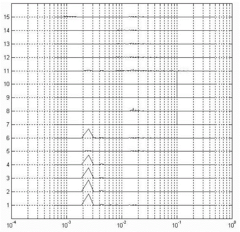
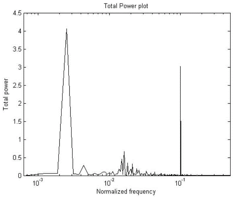
[0017] Secondly, for the data set A, combined with frequency-domain non-negative matrix factorization (NMF) or frequency-doma...


PUM


Abstract

The invention discloses a method for positioning a plant-level control loop oscillation source of process industry. The method comprises the following steps: with respect to a multi-loop control system, constructing an original loop variant data set including a plurality of loop signal oscillations; processing the original loop variant data set by adopting a frequency domain-based nonnegative matrix decomposition or frequency domain-based independent component analysis method, and extracting one or more to-be-detected loop sets containing the same frequency band; calculating a two-dimensional united probability distribution curved surface of a controller output quantity and a controlled quantity of each loop in the to-be-detected loop sets, to acquire a corresponding maximum on the two-dimensional united probability distribution curved surface of controller output quantities and controlled quantities of all loops in each to-be-detected loop set. Compared with the prior art, the method has the advantage of high accuracy, can be used for effectively positioning a plant-level control loop oscillation source, and provides great convenience for eliminating harm caused by plant-level control loop oscillations.

Description

technical field [0001] The invention belongs to the field of control or regulation systems, in particular to a process industry plant-level control loop oscillation source positioning method based on a model identification method. Background technique [0002] Due to the increasing complexity of the modern process industry and the lack of daily maintenance of the controller, industrial processes such as electric power, petroleum, chemical industry, steel, paper, cement, etc. generally have poor control loop performance. Foreign studies have shown that there are 1 The control loop of / 3 is in an oscillating state. Loop oscillation is an obvious manifestation of control performance degradation. There are many possible causes of control loop oscillation: non-linear faults in the control valve, such as friction, dead zone, recoil and sticking; control parameter adjustment Inappropriate, which makes the system tend to be unstable and cause oscillation; from external oscillation ...

Claims


Application Information

Patent Timeline
Patent Type & Authority Patents(China)
IPC IPC(8): G05B23/02
CPCG05B23/0245G05B23/0278
Inventor 曹鸣
Owner SOUTHEAST UNIV
Why Eureka
Try Eureka