Array substrate and driving method therefor and display device

An array substrate and display area technology, applied in static indicators, nonlinear optics, instruments, etc., can solve the problem that the display panel cannot achieve ultra-narrow bezel or zero bezel

Inactive Publication Date: 2015-09-09
BOE TECH GRP CO LTD +1
View PDF5 Cites 18 Cited by
  • Summary
  • Abstract
  • Description
  • Claims
  • Application Information

AI Technical Summary

Problems solved by technology

This also makes it impossible to achieve ultra-narrow bezels or zero bezels on multiple sides of the display panel

Method used


Image

  • Array substrate and driving method therefor and display device
  • Array substrate and driving method therefor and display device
  • Array substrate and driving method therefor and display device

Examples


Embodiment 1

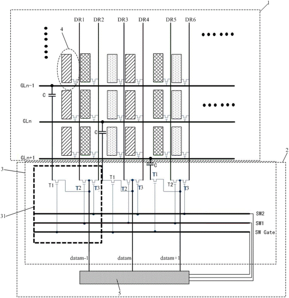
[0034] This embodiment provides an array substrate, such as figure 2 As shown, it includes an array of pixel units 4 arranged in the display area 1, a plurality of gate lines GL and a plurality of data lines DR, each gate line GL is correspondingly connected to a row of pixel units 4, and each data line DR is correspondingly connected to a column of pixel units 4 , also includes the first drive circuit 3 arranged in the non-display area 2 outside the display area 1 side, the first drive circuit 3 is connected with each gate line GL and each data line DR respectively, and is used for the gate line GL and each data line DR The data line DR provides a driving signal.

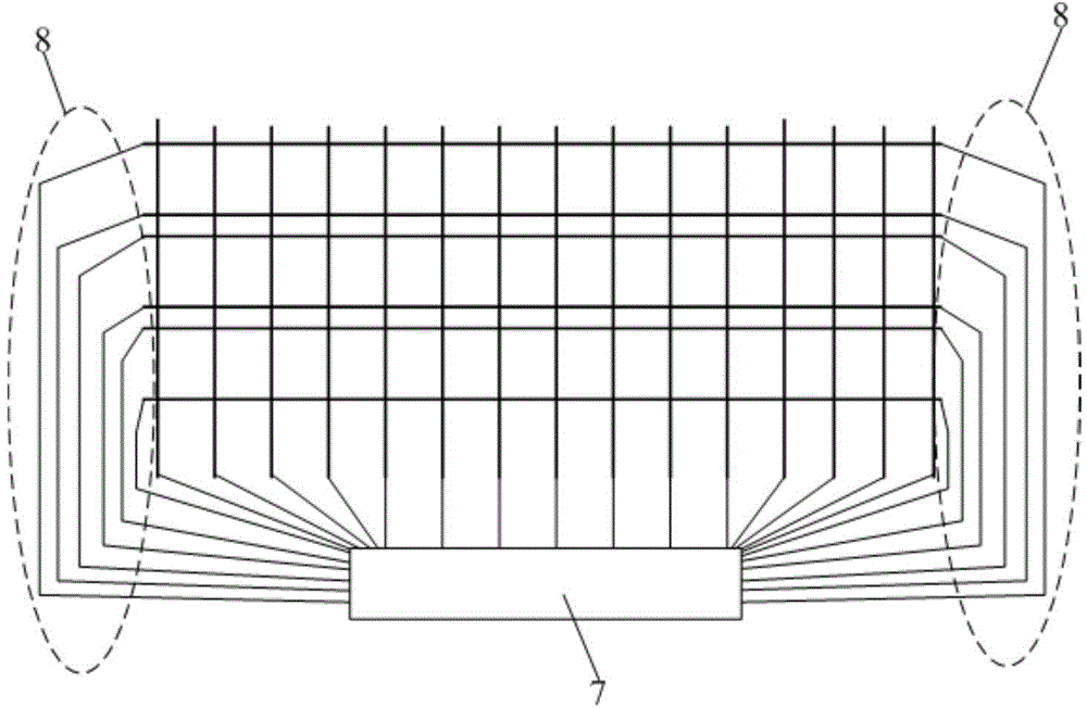
[0035] The array substrate can drive all the gate lines GL and data lines DR on the array substrate by setting the first drive circuit 3 in the non-display area 2 outside the display area 1, thereby avoiding multiple Side wiring, so that the array substrate can realize zero borders on all sides except one side. ...

Embodiment 2

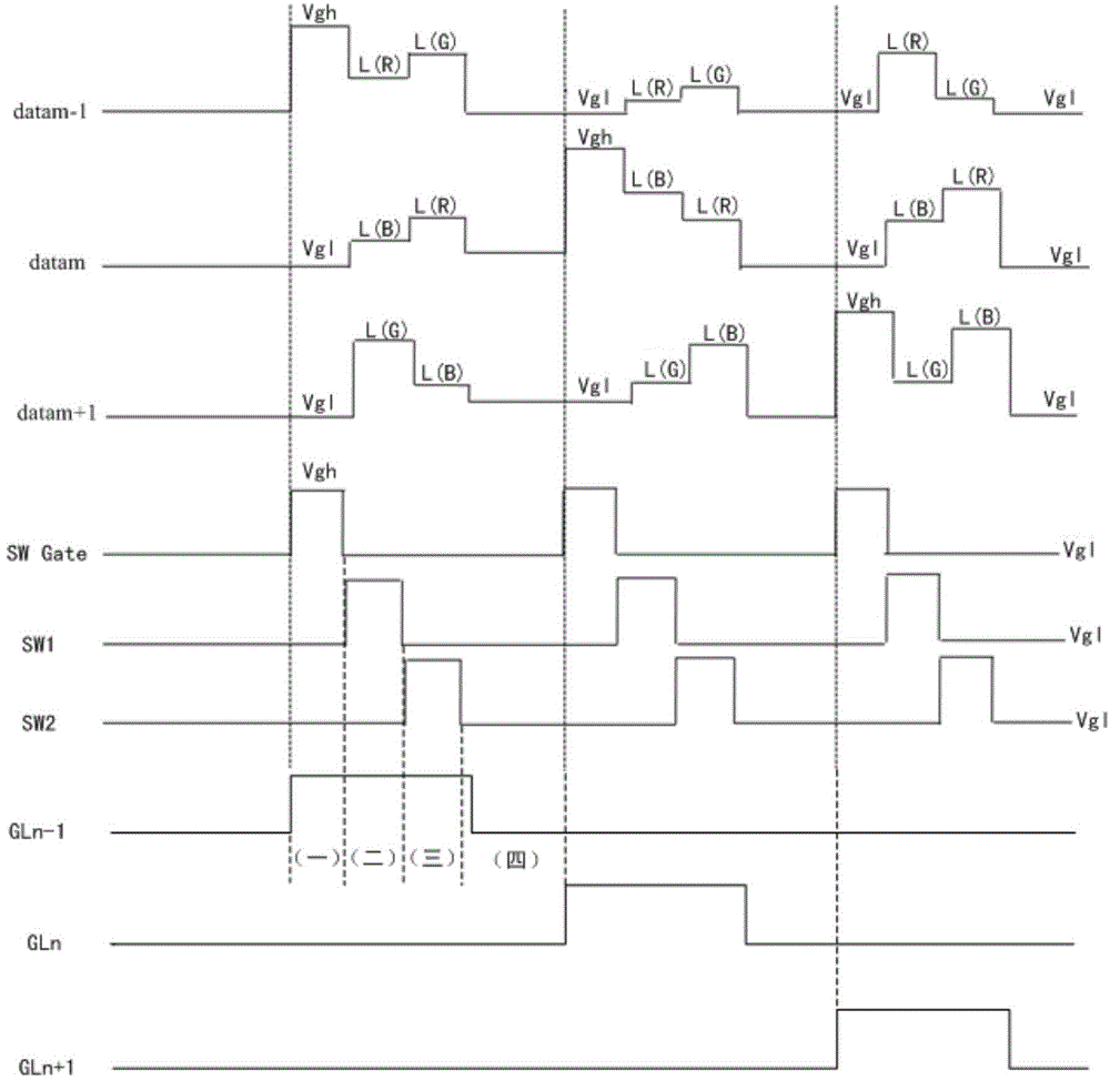
[0056] This embodiment provides an array substrate, and the difference from Embodiment 1 is that, as Figure 4 As shown, the array substrate also includes a data driving circuit 5 and a peripheral circuit 6, the data driving circuit 5 and the first driving circuit 3 are arranged in the non-display region 2 outside the same side of the display region 1; the peripheral circuit 6 is arranged outside the array substrate; A control signal line SW Gate, the second control signal line SW1 and the third control signal line SW2 are connected with the peripheral circuit 6, and the peripheral circuit 6 is used for controlling the first control signal line SW Gate, the second control signal line SW1 and the third control signal line SW2. The signal line SW2 provides a control driving signal; the data signal line data is connected to the data driving circuit 5, and the data driving circuit 5 is used to provide the data driving signal for the data signal line data.

[0057] Wherein, the dat...

Embodiment 3

[0061] This embodiment provides a display device, including the array substrate in any one of Embodiments 1-2.

[0062] By adopting the array substrate in any one of Embodiments 1-2, the display device can realize a narrow frame on the side where the driving circuit is provided and a zero frame on the other sides except this side, and at the same time, the display device will not be degraded. The resolution of the device.

[0063] The display device provided by the present invention can be any product or component with a display function such as a liquid crystal panel, a liquid crystal television, a monitor, an OLED panel, an OLED television, a mobile phone, and a navigator.


PUM


Abstract

The invention provides an array substrate and a driving method therefor and a display device. The array substrate comprises a pixel cell array, a plurality of grid lines and a plurality of data lines, wherein the pixel cell array, the grid lines and the data lines are arranged in a display area; each grid line is correspondingly connected with a row of pixel cells, and each data line is correspondingly connected with a column of pixel cells. The array substrate further comprises a first driving circuit which is arranged in a non-display area outside one side of the display area, wherein the first driving circuit is connected with each grid line and each data line respectively and is used for providing driving signals for the grid lines and the data lines. According to the array substrate, the first driving circuit is arranged in the non-display area outside one side of the display area, then, all the grid lines and all the data lines on the array substrate can be driven, thus, the wiring for multiple sides of the array substrate is avoided, and then, zero frame for other sides of the array substrate except for one side can be realized; and meanwhile, narrow frame for the side, where the first driving circuit is arranged, of the array substrate can also be realized.

Description

technical field [0001] The present invention relates to the field of display technology, in particular, to an array substrate, a driving method thereof, and a display device. Background technique [0002] With the development of display technology, the requirements for high-quality display devices are getting narrower and narrower. High-end display devices such as wearable displays and special-shaped displays equipped on car dashboards are all pursuing ultra-narrow bezels or even no bezels. [0003] Display panels in traditional display devices (such as mobile phones) such as figure 1 As shown, the driving chip 7 is arranged on one side of the non-display area of ​​the display panel, and the driving chip 7 is used to provide scanning driving signals and data driving signals to the pixels arranged in the display area. Scanning signal lines 8 for transmitting scanning driving signals need to be arranged in the border non-display area on other sides of the display panel, which...

Claims


Application Information

Patent Timeline
Patent Type & Authority Applications(China)
IPC IPC(8): G09G3/20
CPCG02F1/13454G09G3/3648G09G2300/0408G09G2300/0426G09G2310/0281G02F1/13456
Inventor 许睿董学陈小川王磊苗京花杨明
Owner BOE TECH GRP CO LTD
Why Eureka
Try Eureka