
Device and method for realizing photoinduced rotation based on double-beam light trap

A photo-rotation, double-beam technology, applied in the field of optical micro-manipulation systems, can solve the problems of inconvenient operation, low measurement accuracy, low rotation speed, etc., and achieve the effects of simple and convenient operation, high control accuracy, and long working distance

Active Publication Date: 2015-09-09
NAT UNIV OF DEFENSE TECH
View PDF6 Cites 21 Cited by
  • Summary
  • Abstract
  • Description
  • Claims
  • Application Information

AI Technical Summary

Problems solved by technology

The double-beam misalignment method has no restrictions on the material and shape of the manipulated particles, and has a wide range of application prospects, but this method has the following disadvantages: (1) The misalignment distance is difficult to control, and when the misalignment distance is too large, it cannot be stably captured For particles, when the misalignment distance is too small, the rotation speed is very small; (2) This method realizes photoinduced rotation through the transmission of linear momentum, and cannot achieve high-speed and stable rotation of particles; (3) uses optical imaging to measure the particle speed, and the measurement accuracy lower
At present, the use of spin angular momentum transfer to achieve photorotation is based on the single-beam gradient force optical trap (optical tweezers) system, which has the following disadvantages: (1) The single-beam photorotation technology requires a highly focused laser beam to form a larger Gradient force, which is easy to damage living cells, is not conducive to the rotation control of living cells; (2) the working distance of single-beam photorotation technology is limited by the focal length of the focusing lens, the effective working distance is short, and the operation is inconvenient; (3) the rotation speed measurement and Low control precision

Method used


Image

  • Device and method for realizing photoinduced rotation based on double-beam light trap

Examples


Embodiment Construction

[0029] The present invention will be further described below in conjunction with the accompanying drawings, but the protection scope of the present invention should not be limited thereby.

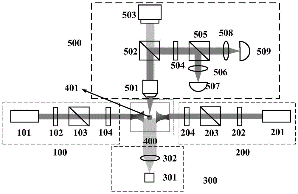
[0030] refer to figure 1 , the device for realizing photorotation based on the double-beam optical trap of the present invention is composed of the No. 1 beam adjustment system 100 , the No. 2 beam adjustment system 200 , the illumination system 300 , the sample cell 400 and the rotational speed measurement system 500 . The two sets of beam adjustment systems 100 and 200 respectively output left-handed and right-handed circularly polarized light with equal power and different wavelengths, and input the two beams of left-handed and right-handed circularly polarized light as captured light into the sample cell 400 and align them for Trapping and spinning birefringent material particles. The illumination system 300 is used to provide illumination below the sample cell, and the rotation speed...


PUM


Abstract

The invention relates to a device and method for realizing photoinduced rotation based on double-beam light trap, belonging to the technical field of optical micro-control systems. The device is composed of two light beam adjusting systems, a sample cell, an illumination system and a rotating speed measuring system. The two light beam adjusting systems respectively generate leftward-rotation circularly polarized light and rightward-rotation circularly polarized light which are the same in power but different in wavelengths, the two beams of circularly polarized light are input at the two sides of the sample cell and aligned to capture and rotate particles of birefringence material, the illumination system under the sample cell provides illumination, and the rotating speed measuring system over the sample cell is used to observe and measure the rotating speed of the particles of the birefringence material. The device and method have the advantages of higher control precision, higher rotating speed of the particles and higher stability.

Description

technical field [0001] The invention belongs to the technical field of optical micro-manipulation systems, and in particular relates to a device and method for realizing light-induced rotation based on a double-beam optical trap. Background technique [0002] The angular motion of mesoscopic particles is one of the basic problems in physics and fluid mechanics. Controlling the angular motion of mesoscopic particles is crucial for the research of biological cells, biomacromolecules and nanomotors, as well as the precise measurement of material properties in the microscopic field. has very important applications. However, it is difficult for particles at this scale to achieve angular motion manipulation by macroscopic means. [0003] Photoinduced rotation is a mesoscopic-scale particle angle control technology developed on the basis of optical tweezers, which uses optical force or torque to achieve particle rotation control. As we all know, besides carrying linear momentum, ...

Claims


Application Information

Patent Timeline
IPC IPC(8): G21K1/00
CPCG21K1/00
Inventor 肖光宗陈鑫麟熊威刘海军张莹罗晖
Owner NAT UNIV OF DEFENSE TECH
Learn More