High-speed branching device of stranding machine

A technology of stranding machine and wire splitter, which is applied in the field of stranding machines, can solve problems such as uneven lay length of copper strands and uneven distribution of copper wires, and achieve the goals of improving efficiency, reducing mutual wear, and reducing wear Effect

Active Publication Date: 2015-09-09
重庆星达铜业有限公司
View PDF5 Cites 4 Cited by
  • Summary
  • Abstract
  • Description
  • Claims
  • Application Information

AI Technical Summary

Problems solved by technology

Before multiple copper wires enter the stranding machine for compounding process, the copper wires will pass through the separation of the distribution board and then gather together to ensure that the laying distance of each part of the same copper strand is the same; but for large During the twisting process of the diameter copper stranded wire, a large number of copper wires will pass through the distribution board, while the number of holes on the ordinary distribution board is fixed, and radial jumps will occur during the movement of the copper wires. The local twist distance on the copper stranded wire is different, that is, the distribution of each copper wire is uneven, which directly leads to the poor performance of the copper stranded wire.

Method used


Image

  • High-speed branching device of stranding machine
  • High-speed branching device of stranding machine
  • High-speed branching device of stranding machine

Examples


Embodiment 1

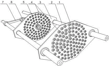
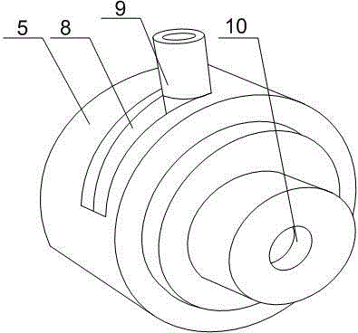
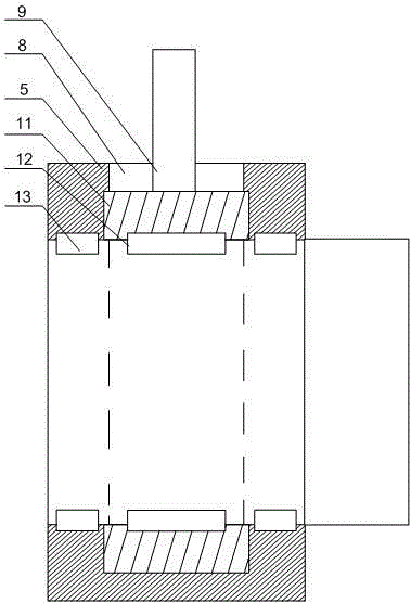
[0022] Such as Figure 1~Figure 3 As shown, this embodiment includes a bracket 2 and a branching board 1 and a reserve board 3 that are sequentially fixed on the bracket 2 along the copper wire feed direction. A plurality of branching boards 1 and the reserve board 3 are provided. In the cable hole 4, a cable feeder 5 is fixed at the axis of the reserved plate 3, and two connecting rods 7 are slidably arranged on the bracket 2, and the movable ends of the two connecting rods 7 pass through the adjusting ring 6 Are connected to each other, the adjusting ring 6 is provided with an inlet hole 9 and an inner conical surface 11 is arranged on the upper part of the inlet hole 9, and a plurality of balls 10 are arranged at the lower part of the inlet hole 9; The inner wall is rotatably provided with an adjusting ring 11 with the same inner diameter. An arc-shaped slot 8 is opened on the outer wall of the wire feeder 5. The push rod 9 penetrates the arc-shaped slot 8 and is connected t...


PUM


Abstract

The invention discloses a high-speed branching device of a stranding machine. The branching device comprises a carriage, a branching plate and a reserved plate, wherein the branching plate and the reserved plate are successively fixed on the carriage along the copper wire inlet direction, each of the branching plate and the reserved plate is provided with wire through holes, a wire inlet unit is fixed at the axial center of the reserved plate, and the carriage is provided with two connecting rods in a sliding manner. The moving ends of the two connecting rods are connected with each other via an adjusting loop, a wire inlet is formed in the adjusting loop, the upper portion of the wire inlet is provided with an inner conical surface, and the lower portion of the wire inlet is provided with balls. The inner wall of the wire inlet unit is rotatably provided with an adjusting ring whose internal diameter is the same with that of the wire inlet unit, an arc chute is formed in the outer wall of the wire inlet unit, and a push rod is connected with the adjusting ring by penetrating the arc chute. The adjusting loop is slidably arranged on the carriage via the connecting rod, thus, the adjusting loop can be slid according to the practical diameter of copper wires, and wearing between the copper wires and the wire inlet as well as an upper inlet of the twisting machine can be reduced.

Description

Technical field [0001] The invention relates to a stranding machine, in particular to a high-speed stranding machine splitter. Background technique [0002] When the copper wire passes through the twisting bow on the stranding machine, the twisting bow makes each single copper wire spirally wound together through a circular motion; the twisted copper wire is the maximum amount of a single copper wire, and different specifications are different The number of copper wires is twisted together in a certain arrangement order and lay length to become a conductor with a larger diameter. The stranded conductor is much softer than a single copper wire of the same diameter. The bending performance of the wire is also better. The single wire appears once at a fixed distance along the direction of the twisted wire. The fixed distance apart is the pitch of the twisted wire (referred to as the twisted pitch). Another definition of lay length is: refers to the vertical distance that the stran...

Claims


Application Information

Patent Timeline
IPC IPC(8): H01B13/02
Inventor 彭德均
Owner 重庆星达铜业有限公司
Why Eureka
Try Eureka