A solar cell structure

A technology of solar cells and electrode layers, applied in the field of solar cells, can solve the problems of low photoelectric conversion efficiency of ordinary solar cells, and achieve the effects of increasing the number, reducing the cost and reducing the area.

Active Publication Date: 2017-09-19
嘉兴巨腾信息科技有限公司
View PDF9 Cites 0 Cited by
  • Summary
  • Abstract
  • Description
  • Claims
  • Application Information

AI Technical Summary

Problems solved by technology

[0008] In order to solve the problem of low photoelectric conversion efficiency of existing ordinary solar cells, the present invention provides a solar cell structure in which the lower electrode layer in the ordinary solar cell structure is changed, the lower electrode layer is arranged on the periphery of the upper electrode layer, and the lower electrode layer can be Completely surround or partially surround the projection of the upper electrode layer on the lower electrode layer, so that the distribution of the electric field in the ferroelectric material layer is no longer uniform, perpendicular to the upper and lower electrode layers, but divergent, not perpendicular to the surface of the upper and lower electrode layers , so as to increase the number of carriers separated by the electric field, and finally achieve the effect of enhancing the photovoltaic effect

Method used


Image

  • A solar cell structure
  • A solar cell structure
  • A solar cell structure

Examples


Embodiment Construction

[0025] The present invention will be described in detail below in conjunction with the accompanying drawings and embodiments.

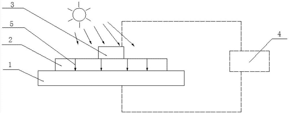
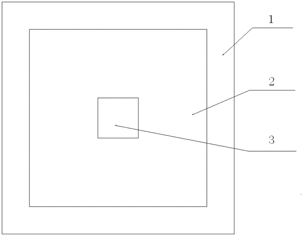
[0026] Such as image 3 , Figure 4 and Figure 5 As shown, a solar cell structure includes an upper electrode layer 3, a lower electrode layer 1 and a ferroelectric material layer 2 arranged between the upper electrode layer 3 and the lower electrode layer 1', and the lower electrode layer 1' is arranged on the outer side of the upper electrode layer 3. Said lower electrode layer 1' completely surrounds the projection of the upper electrode layer 3 on the lower electrode layer 1'. The lower electrode layer 1' partially surrounds the projection of the upper electrode 3 layer on the lower electrode layer 1'. Therefore, the distribution of the electric field 5' in the ferroelectric material layer 2 is divergent and not perpendicular to the surface of the upper and lower electrode layers. Compared with the common solar cell structure of the same ferr...


PUM


Abstract

The invention discloses a solar cell structure, comprising an upper electrode layer, a lower electrode layer and a ferroelectric material layer between the upper electrode layer and the lower electrode layer, wherein the lower electrode layer is arranged on the periphery of the upper electrode layer, and the lower electrode layer can completely or partially surround the projection of the upper electrode layer on the lower electrode layer, so that the electric field in the ferroelectric material layer is scattered and is not perpendicular to the surfaces of the upper and lower electrode layers. The magnetic field in the ferroelectric material layer of a common solar cell structure is changed from a situation that the magnetic field is uniformly scattered and is perpendicular to the surfaces of the upper and lower electrode layers to a situation that the magnetic field is scattered and is not perpendicular to the surfaces of the upper and lower electrode layers, so that the quantity of current carriers separated by the electric field is increased and the photovoltaic effect is finally enhanced.

Description

technical field [0001] The invention belongs to the field of solar cells, and in particular relates to a solar cell structure and a manufacturing method thereof. Background technique [0002] Such as figure 1 and figure 2 The structure of the common solar cell shown has a lower electrode layer 1 , a ferroelectric material layer 2 and an upper electrode layer 3 in sequence from bottom to top. The upper electrode layer 3 and the lower electrode layer 1 are respectively connected to external devices through wires. for figure 1 For example, the ferroelectric material layer is relatively thin, such as 500 nm, and the area of ​​the lower electrode layer is relatively large, such as a square with a side length of 1 cm, and a square with a side length of 200 μm for the upper electrode layer. At such a scale, after the ferroelectric material is polarized by an external electric field, a depolarization field will be generated between the upper and lower electrodes. Since the upp...

Claims


Application Information

Patent Timeline
Patent Type & Authority Patents(China)
IPC IPC(8): H01L31/0224H01L31/18
CPCH01L31/022425H01L31/18Y02E10/50Y02P70/50
Inventor 高荣礼符春林蔡苇邓小玲陈刚
Owner 嘉兴巨腾信息科技有限公司
Why Eureka
Try Eureka