A switch unit structure

A technology of switching units and switching devices, which is applied in the direction of power transmission AC network, etc., can solve the problems of complicated electrical connection of switching devices, large overall space occupation, and low space utilization rate, etc., and achieves compact and beautiful mechanical installation structure, convenient disassembly and maintenance , Insulation coordination is safe and reliable

Active Publication Date: 2017-05-31
RONGXIN HUIKO ELECTRIC TECH CO LTD +1
View PDF4 Cites 0 Cited by
  • Summary
  • Abstract
  • Description
  • Claims
  • Application Information

AI Technical Summary

Problems solved by technology

The disadvantages of this structure are that the layout is simple, the overall space is large, the electrical connection is complicated, and the disassembly and maintenance are inconvenient, resulting in increased loss and waste of space.
[0003] At the same time, the installation structure of press-fit devices used in the past is a structure in which preload is applied by several screws, and other devices are distributed outside, and the space utilization rate is also not high.
And the outstanding problem is that the conductive contact of this structure is uneven, which can easily cause poor contact or compress and deform the device, directly affect the electrical performance or even burn out the device.
[0004] In the prior art, the diodes, resistors, and capacitors of the voltage equalizing device are scattered and arranged on the overall structure according to the specific spatial structure of the device after the switching device is installed, which causes the spatial layout to be messy, and the electrical connection with the switching device It is also relatively cumbersome, and the layout of the insulation structure needs to be improved

Method used


Image

  • A switch unit structure
  • A switch unit structure
  • A switch unit structure

Examples


Embodiment Construction

[0026] The present invention will be described in detail below in conjunction with the accompanying drawings, but it should be pointed out that the implementation of the present invention is not limited to the following embodiments.

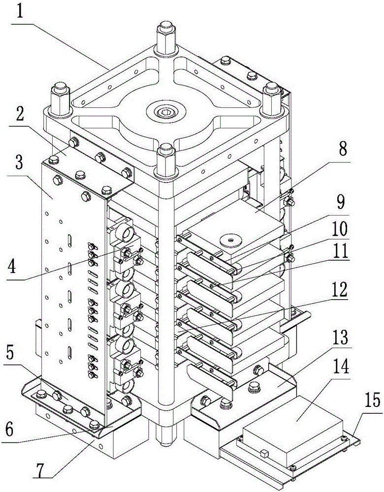
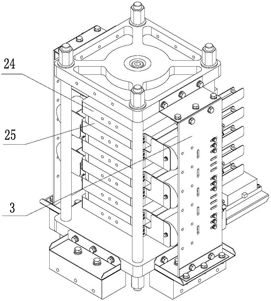
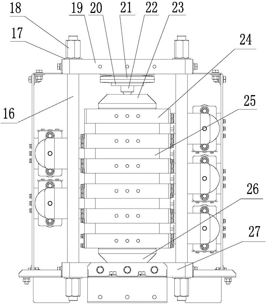
[0027] See Figure 1-Figure 7 , a switch unit structure, including a press-fit switch device structure 1, a voltage equalizing device structure 4, a device driver 8, a drive clamp 9 and a drive power supply 14, the overall frame is composed of a resin support plate 16, and end plates I located on the upper and lower sides 19 and end plate II 27, on both sides of the overall frame there are pressure equalizing device support plates 3, the upper part of the pressure equalizing device structural support plate 3 is fixed with the end plate I19 through the upper support 2, and the lower part of the pressure equalizing device structural support plate 3 The support seat I6 and the support plate corner piece 5 are fixed to the end plate II 27, the device...


PUM


Abstract

The invention relates to a switch unit structure. The switch unit structure includes a press mounting switch device, voltage balancing devices, a device drive, a drive clamp, and a drive power supply. The switch unit structure is characterized in that the press mounting switch device is arranged inside the whole structure, the voltage balancing devices are assembled to be a voltage balancing device integrated modularized structure through press mounting members and are arranged on two sides of a frame structure of the press mounting switch device through structure supporting plates, the device drive is connected at one side of the switch device, and then an integrated compact switch unit structure is formed. The advantages of the switch unit structure are that the switch device and a radiator member are arranged inside the frame via a press mounting mechanism, the voltage balancing devices are assembled to be a whole structure through the press mounting members, and the voltage balancing devices are arranged on the entire press mounting mechanism through buses, so the switch unit structure is compact in structure and reliable in electrical connection, is convenient to mount, dismount and maintain, and exhibits good properties; and the supporting structures are made from high-strength insulating materials, so the insulating coordination dimension of the whole structure is effectively reduced.

Description

technical field [0001] The invention relates to a switch unit structure, in particular to a switch unit structure used in the field of flexible direct current transmission. Background technique [0002] With the continuous development of power electronics technology, the performance of power components is constantly upgraded, and the size is also getting larger and larger. The spatial layout of the overall structure, the reliable contact of the conductive contact surface, and the heat dissipation capacity of the radiator are particularly important for the electrical performance. Usually, the structural layout of the switching unit is generally to simply install and fix the switching device and the cooling device, and then form a topological circuit through electrical connection. The disadvantages of this structure are that the layout is simple, the overall space is large, the electrical connection is complicated, disassembly and maintenance are inconvenient, resulting in in...

Claims


Application Information

Patent Timeline
Patent Type & Authority Patents(China)
IPC IPC(8): H02J3/36
CPCY02E60/60
Inventor 李庆宇刘伟王强龙浩张海涛易荣赵明宇刘国伟姚森敬
Owner RONGXIN HUIKO ELECTRIC TECH CO LTD
Why Eureka
Try Eureka