
Pre-charging device and method of electric automobile

An electric vehicle and pre-charging technology, applied in electric vehicles, battery circuit devices, circuit devices, etc., can solve the problems of inability to meet the requirements of high-voltage power-on time, affecting charging speed, and small charging current, so as to improve user experience and improve user experience. Vehicle performance, the effect of shortening the high-voltage pre-charge time, and shortening the high-voltage power-on time

Inactive Publication Date: 2015-09-09
BEIQI FOTON MOTOR CO LTD
View PDF6 Cites 26 Cited by
  • Summary
  • Abstract
  • Description
  • Claims
  • Application Information

AI Technical Summary

Problems solved by technology

However, in the charging process, the capacitor is pre-charged through the formed RC loop. As the voltage at the capacitor terminal increases, the charging current will decrease, and the charging current will be very small in the later stage of charging.
This makes the pre-charging time too long when the voltage platform of the electric vehicle is high and the front-end capacitance of the motor controller is large, which cannot meet the vehicle's requirements for high-voltage power-on time
For example, if the resistance R1 in this scheme is selected to be small, the initial charging current will be large, and the circuit will be easily burned. If the resistance R1 is selected too large, the charging speed will be slow in the later stage of charging, which will affect the charging speed.
It can be seen that the resistor R1 in this scheme cannot make the precharging process complete smoothly and efficiently

Method used


Image

  • Pre-charging device and method of electric automobile
  • Pre-charging device and method of electric automobile
  • Pre-charging device and method of electric automobile

Examples


Embodiment 1

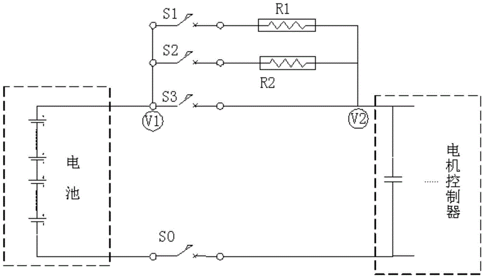
[0039] A kind of electric vehicle precharging device is provided in this embodiment, such as figure 1 As shown, it includes a battery system and a load circuit. The negative output terminal of the battery system is connected to the negative terminal of the load circuit through a controllable switch S0, and the positive output terminal of the battery system is connected to the positive terminal of the load circuit. terminals are connected through the S3 switch, and there is also a multi-stage pre-charging circuit connection between the positive output terminal of the battery system and the positive terminal of the load circuit, and the multi-stage pre-charging circuit can provide variable resistance as required Resistance value, the multistage precharge circuit in the present embodiment comprises:

[0040] Two pre-charging circuits are arranged in parallel between the positive output end of the battery system and the positive connection end of the load circuit, and each pre-cha...

Embodiment 2

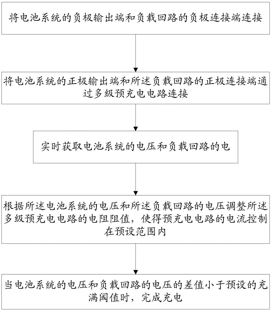
[0044] In this embodiment, a pre-charging control method for an electric vehicle is provided, which is used for figure 1 In the pre-charging device of , comprise the following steps:

[0045] First, after receiving the high-voltage power-on command, the battery management system closes the negative contactor S0, and connects the negative output terminal of the battery system to the negative terminal of the load circuit.

[0046] Then, obtain the voltage of the battery system and the voltage of the load circuit in real time;

[0047] Next, according to the voltage of the battery system and the voltage of the load circuit, the current state of the system is determined, and a pre-charging mode for starting pre-charging is selected. According to the selected pre-charging mode, the corresponding pre-charging circuit is connected, the equivalent resistance value in the pre-charging circuit is changed, and the voltage increase of the load circuit is controlled.

[0048] During the ...

Embodiment approach

[0055] As a specific implementation, the process is as follows:

[0056] The specific steps are as follows:

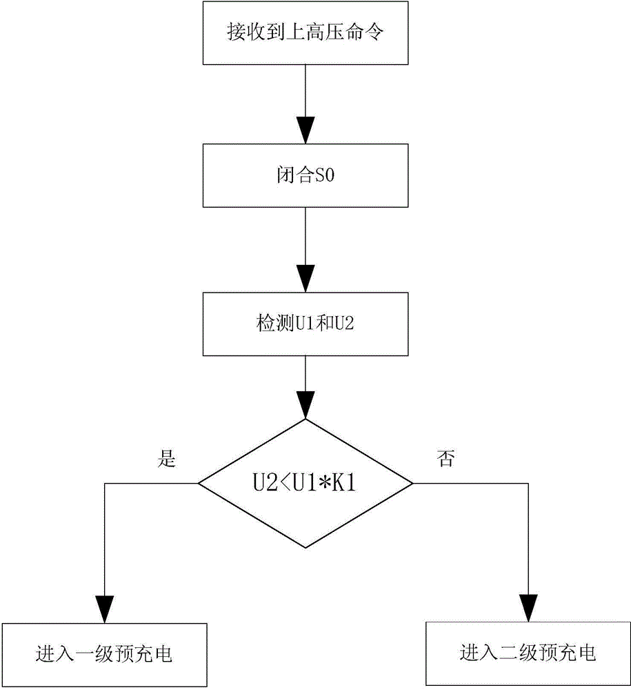
[0057] First, detect battery-side voltage U1 and load-side voltage U2, and compare U1 and U2. If U2U1*K1, enter the second-level pre-charging mode, where K1 is the calibration coefficient. Such as image 3 shown.

[0058] When starting to charge U2<U1*K1, when entering the first-level pre-charging mode, close S1. At this time, S1 is closed, S2 is opened, and the high-voltage circuit is pre-charged through the pre-charging resistor R1.

[0059] The U2 voltage is monitored as the precharge progresses. When U2>U1*K2, enter the three-level pre-charging mode and close S2. At this time, S1 is closed, S2 is closed, and the high-voltage circuit is pre-charged through the pre-charging resistance connected in parallel between R1 and R2, such as Figure 4 shown. This can increase the pre-charging current and quickly increase the voltage across the capacitor.

[0060] If ...


PUM


Abstract

The invention provides a pre-charging device and method of an electric automobile. The cathode output end of a battery system is connected with the cathode connection end of a load loop via a controllable switch, and the anode output end of the battery system is connected with the anode connection end of the load loop via a multilevel pre-charging circuit. The multilevel pre-charging circuit can control the resistance of pre-charging resistors in the circuit according to requirements, and further controls the whole pre-charging process. According to the voltage of the battery system and the voltage of the load loop, different pre-charging modes are selected to adjust the resistance of the pre-charging resistors of the multilevel pre-charging circuit, control the pre-charging process, and rapidly improve the voltage of the load loop. According to the multilevel pre-charging method, the pre-charging resistance of the pre-charging loop can be controlled at proper time, the voltage of the load loop is improved, the pre-charging process is optimized, and on the premise that the safety is ensured, time of high-voltage pre-charging is shortened, the whole high-voltage power one time is shortened, and user experience and vehicle performance are improved.

Description

technical field [0001] The invention relates to the field of electric vehicles, in particular to an electric vehicle precharging device and method. Background technique [0002] Electric vehicles use power batteries as energy to drive the motor to achieve the purpose of driving the electric vehicle. The work of the electric vehicle motor is controlled by the motor controller. There are many large capacitors for filtering and voltage stabilization inside the motor controller. The positive pole is connected to the positive pole of the storage battery through a switch. Other high-voltage point devices in the vehicle, such as DC / DC converters, accessory motor controllers, etc., also have front-end capacitors. When the switch is directly turned on, the battery will instantly charge the capacitor with a very large current, and the impact will affect the life of the capacitor and the reliability of the controller. [0003] In order to ensure the safety of the system, when the bat...

Claims


Application Information

Patent Timeline
IPC IPC(8): H02J7/00
Inventor 赵祥日闫丽娟
Owner BEIQI FOTON MOTOR CO LTD
Learn More