A Permanent Magnet Assisted Synchronous Reluctance Motor Rotor for High Speed ​​Applications

An auxiliary synchronous and reluctance motor technology, applied in synchronous machine parts, magnetic circuit rotating parts, magnetic circuit shape/style/structure, etc. Suitable for mass production and other issues, to achieve the effect of high cost performance and easy procurement management

Active Publication Date: 2017-10-27
SHANGHAI GIE EM
View PDF5 Cites 0 Cited by
  • Summary
  • Abstract
  • Description
  • Claims
  • Application Information

AI Technical Summary

Problems solved by technology

[0004] Publication Nos. CN104038011A and CN104052227A disclose two kinds of permanent magnet assisted synchronous reluctance motors in the open specifications of Chinese patents. Similarly, the magnet steel adopts the rare earth NdFeB permanent magnet material with high remanence Br, and the amount of magnet steel is large. There are many specifications, except that the magnetic steel in the first layer of magnetic barrier can effectively output a certain amount of magnetic energy when facing the air gap, and the utilization rate of the magnetic energy of the other magnetic steel is low
Compared with the general IPM motor, this structure only slightly increases the limited torque density, but greatly increases the cost of the motor, and the economy is poor, so it is not suitable for mass production
[0005] Publication Nos. CN102761222A and CN102790457A disclose two kinds of permanent magnet assisted synchronous reluctance motors in the open specifications of the Chinese patents. Inexpensive ferrite magnets are embedded in the magnetic barrier. Because the ferrite permanent magnet material is hard and brittle, Electric processing cannot be performed, and only slicing and a small amount of grinding can be performed, so the production process of arc-shaped ferrite magnets is cumbersome and the processing cost is high; meanwhile, ferrite magnets have a large span and are easily broken; The barrier lacks a magnetic bridge to reduce the edge stress of the rotor during high-speed rotation, and there may be a danger of the edge of the rotor being broken, which is not suitable for high-speed working conditions

Method used


Image

  • A Permanent Magnet Assisted Synchronous Reluctance Motor Rotor for High Speed ​​Applications
  • A Permanent Magnet Assisted Synchronous Reluctance Motor Rotor for High Speed ​​Applications
  • A Permanent Magnet Assisted Synchronous Reluctance Motor Rotor for High Speed ​​Applications

Examples


Embodiment Construction

[0032] In order to make the technical means, creative features, goals and effects achieved by the present invention easy to understand, the present invention will be further described below in conjunction with specific illustrations.

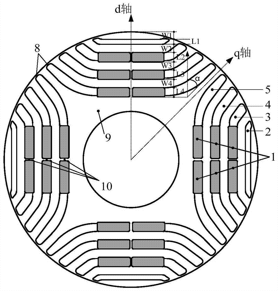
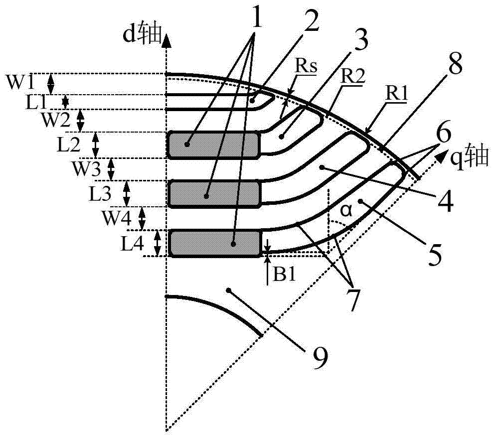
[0033] Refer to attached figure 1 , which is a structural schematic diagram of the permanent magnet assisted synchronous reluctance motor rotor that can be used in high-speed applications provided by the present invention. It can be seen from the figure that the permanent magnet assisted synchronous reluctance motor rotor mainly includes three parts: the rotor yoke (ie, the rotor core), the magnetic barrier disposed on it, and the magnetic steel disposed in the magnetic barrier.

[0034] Among them, the motor rotor scheme distributes four layers of boat-shaped magnetic barriers under each pole of the rotor core 9, and the scheme shown in the figure arranges four layers of boat-shaped magnetic barriers symmetrically in the four pole directions of...


PUM


Abstract

The invention discloses a permanent magnet assisted synchronous reluctance motor rotor which can be used in high-speed occasions. The permanent magnet assisted synchronous reluctance motor rotor includes a rotor core, a magnetic barrier distributed on the rotor core, and a magnetic barrier arranged in the magnetic barrier. Steel; four layers of boat-shaped magnetic barriers are distributed under each pole of the rotor core, and each layer of magnetic barriers is connected and closed by a straight line part in the middle and perpendicular to the d-axis and an oblique straight line part at both ends and at an angle α to the d-axis made. The invention optimizes the design of the motor rotor, so that the motor has the characteristics of high efficiency, high torque density, high power factor, strong anti-demagnetization ability and convenient manufacture.

Description

technical field [0001] The invention relates to the technical field of synchronous motors, in particular to a permanent magnet assisted synchronous reluctance motor rotor. Background technique [0002] The synchronous reluctance motor relies entirely on the reluctance difference of the dq axis magnetic circuit to generate torque. Because there is no guide bar on the rotor, there is no electromagnetic loss, and it has higher efficiency and lower stable operating temperature than induction motors. Through the optimal design of the magnetic barrier of the synchronous reluctance motor rotor, the reluctance torque is maximized, and the torque density can be better than that of the induction motor. At present, the problem that restricts the wide application of synchronous reluctance motors is mainly the low power factor, which needs to be driven with a large-capacity inverter. The permanent magnet assisted synchronous reluctance motor can effectively improve the power factor by ...

Claims


Application Information

Patent Timeline
Patent Type & Authority Patents(China)
IPC IPC(8): H02K1/27H02K1/28H02K21/02
Inventor 杨俊勤徐立伟陈永浩张东
Owner SHANGHAI GIE EM
Why Eureka
Try Eureka