A three-level laminated busbar for suppressing stray inductance

A technology of laminated busbars and stray inductance, applied in the modification of power electronics, electrical components, output power conversion devices, etc., can solve the problem of high stray inductance of the commutation circuit, time-consuming and laborious disassembly and handling, and irrelevant capacitor placement Polarity and other issues to achieve the effect of maximizing the overall output capability and reducing stray inductance

Active Publication Date: 2021-06-08
NARI TECH CO LTD +1
View PDF0 Cites 0 Cited by
  • Summary
  • Abstract
  • Description
  • Claims
  • Application Information

AI Technical Summary

Problems solved by technology

[0003] The current three-level stacked busbars have the following problems: 1. The supporting capacitor and the IGBT module are integrated, and it takes time and effort for one person to disassemble and transport, and it is extremely inconvenient to maintain and disassemble; 2. The polarity is not considered when placing capacitors. The stray inductance of the commutation circuit is high; 3. There are too many components and the cost is extremely high
[0004] The existing technology takes into account the optimal design of the three-level busbar and the suppression of stray inductance, but does not address the characteristics of the three-level commutation circuit and symmetrically suppress the problem of stray inductance

Method used


Image

  • A three-level laminated busbar for suppressing stray inductance
  • A three-level laminated busbar for suppressing stray inductance
  • A three-level laminated busbar for suppressing stray inductance

Examples


Embodiment Construction

[0025] The technical solutions of the present invention will be further described below in conjunction with the accompanying drawings and embodiments.

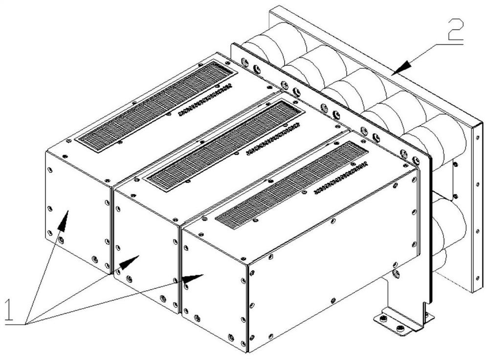
[0026] Such as figure 1 As shown, the three-level laminated busbar described in the present invention adopts the structure independently designed by A, B, C three-phase power module 1 and DC support capacitor module 2, and the A, B, C three-phase power module is Same design.

[0027] The level of the three-level layer adopts a seven-layer pressing design. From the top layer to the bottom layer, they are: insulating layer, positive layer, insulating layer, neutral layer, insulating layer, negative layer, and insulating layer.

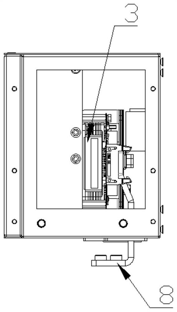
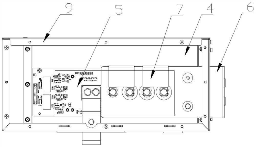
[0028] Such as figure 2 , image 3 with Figure 4 As shown, the A, B, and C three-phase power module 1 is designed as a sheet metal frame 9, with a power module stacked busbar 6 inside the frame, an air-cooled radiator 4 at the bottom, and a power module stacked busbar 6 from the left From the righ...


PUM


Abstract

The invention discloses a three-level laminated busbar for suppressing stray inductance, which includes A, B, and C three-phase power modules and a DC support capacitor module; A, B, and C three-phase power modules are equipped with power The stacked busbar of the module, the stacked busbar of the power module is respectively connected to the DC positive pole P, the middle pole O and the negative pole N; the DC support capacitor module includes the stacked busbar of the support capacitor, which takes the vertical center line of the stacked busbar of the support capacitor as the axis, and the DC support capacitor adopts The polarity is reversed; the supporting capacitor stacked busbar of the DC supporting capacitor module is respectively connected to the DC positive pole P, the middle pole O and the negative pole N; the DC side of the power module stacked busbar is an L-shaped design, directly connected to the supporting capacitor stacked busbar Fitting connected. In the present invention, the path length of the positive and negative commutation circuits of the power module is symmetrically designed, the power module is directly connected to the busbar of the DC support capacitor module, and the DC capacitors are arranged in a dispersed polarity, thereby reducing the stray inductance under three-level four-quadrant operation, Maximize the overall output capacity of the converter.

Description

technical field [0001] The invention relates to a stacked busbar device for a power electronic system converter, in particular to a three-level stacked busbar capable of suppressing stray inductance. Background technique [0002] In energy storage converters and other similar AC-DC conversion converters, power units and three-level stacked busbars are often used. A reasonable busbar design can suppress the stray inductance of the three-level busbar and improve the voltage and current operating range of the converter. [0003] The current three-level stacked busbars have the following problems: 1. The supporting capacitor and the IGBT module are integrated. It takes time and effort for one person to disassemble and transport, and it is extremely inconvenient to maintain and disassemble. 2. The polarity is not considered when placing capacitors. This leads to high stray inductance of the commutation circuit; 3. There are too many components and the cost is extremely high. ...

Claims


Application Information

Patent Timeline
Patent Type & Authority Patents(China)
IPC IPC(8): H02M1/00H05K7/20
CPCH02M1/00H05K7/20909
Inventor 侯凯俞普德何安然王后生余谦陈杰刘良蒋应伟
Owner NARI TECH CO LTD
Why Eureka
Try Eureka