
Capacitor with high heat radiation power

A capacitor and high heat dissipation technology, applied in the field of capacitors, can solve the problems of inability to miniaturize equipment, high failure rate, large stray inductance, etc., and achieve the effect of convenient miniaturization design, reduction of installation size, and improvement of heat dissipation power

Active Publication Date: 2009-07-15
佛山市顺德区创格电子实业有限公司
View PDF0 Cites 5 Cited by
  • Summary
  • Abstract
  • Description
  • Claims
  • Application Information

AI Technical Summary

Problems solved by technology

[0003] Generally, the capacitors commonly used in this occasion have a high failure rate, unstable performance, and short life; the failure mechanism is that in this high-current occasion, the heating power of the capacitor is very high, and the heat dissipation of ordinary capacitors is relatively low, resulting in capacitors The heat generation is very serious. If the product works in a high temperature range for a long time, the performance cannot be guaranteed, and the failure rate of thermal breakdown is greatly increased.
[0004] In order to meet the requirements of high voltage and high current, many manufacturers adopt the method of connecting multiple capacitors in parallel on the PCB board, and then connecting several PCB boards in series. Hundreds of capacitors are often used, which takes up a very large volume.
Although this can temporarily meet the needs, but the cost is high, the volume is large, and too many capacitors use large stray inductance, the stability is not high, the life is not long, and the equipment cannot be miniaturized

Method used


Image

  • Capacitor with high heat radiation power
  • Capacitor with high heat radiation power
  • Capacitor with high heat radiation power

Examples


Embodiment Construction

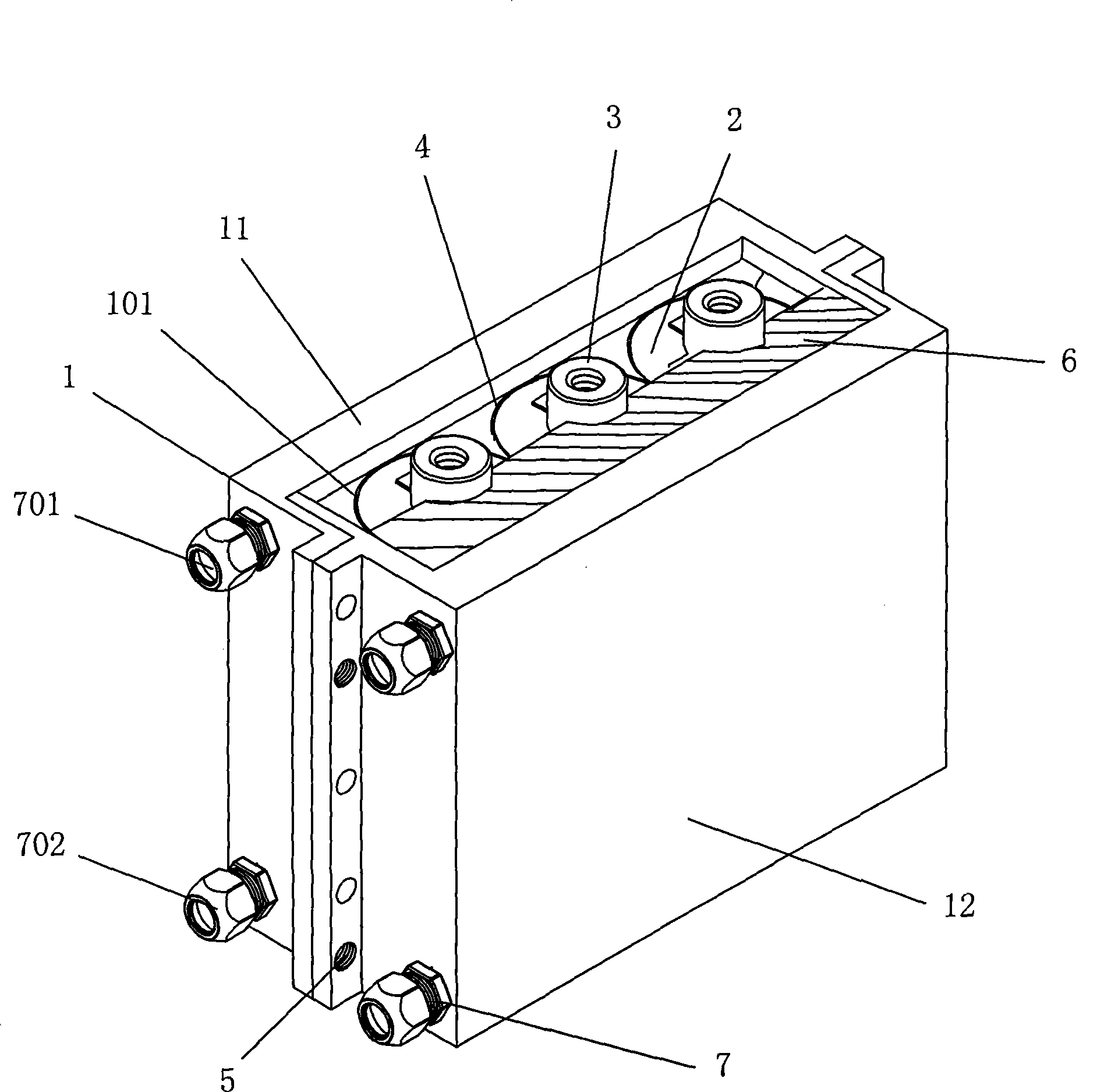
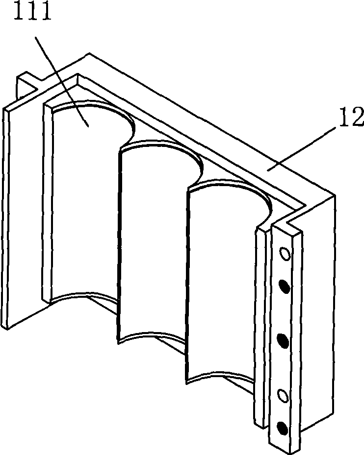
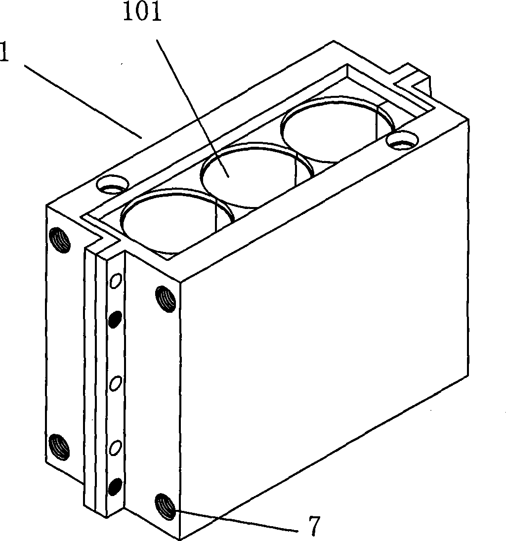
[0029] like Figure 1 to Figure 3 As shown, a capacitor with high heat dissipation power includes a casing 1 and a capacitor core 2 thereof. The casing 1 is composed of two metal shells 11 and 12 with low magnetic permeability. Each metal shell 11 and 12 Both are provided with recesses 111, so that the metal casings 11 and 12 are combined to form the accommodating cavity 101 of the casing 1. The capacitor core 2 is provided with a lead-out end 3, and the capacitor core 2 is covered with an insulating cloth 4 and fitted. In the accommodating cavity 101 , its leading end 3 extends out of the casing 1 , and a fixing member 5 is provided between the combined casings 11 and 12 to connect together. The fixing member 5 can be a screw or a fixing pin. Inside the accommodating cavity 101 The periphery of the capacitor core 2 is also filled with thermally conductive flame retardant resin 6, and each metal shell 11, 12 in the housing 1 is provided with a cooling water channel 7, wherein ...


PUM


Abstract

The present invention relates to a capacitor with high cooling power, including a housing and a capacitor core, wherein, the housing is composed of two low magnetic permeability metal cases, each metal case is provided with a dent, so as to constitute an accommodating cavity by combining the two metal cases, a terminal is provided on the capacitor core, an insulation cloth is provided on the envelop of the core and is jogged in the accommodating cavity, the terminal extending outside the housing, a fixing piece is provided between the mutual combined cases to keep them together, and a heat conducting flame-retarded resin is filled in around the capacitor core in the accommodating cavity. Because the housing is formed by at least two low magnetic permeability metal cases, the capacitor diminish the effects of magnetic induction heating, when the capacitor generates heat during working, the heat is rapidly emitted from the capacitor core surface to the metal cases, as the thermal conductivity factor of the metal case can attain 30 - 100, so the metal cases are taken as heat radiating fins, this structure can effectively improve the overall cooling effect of the capacitor, the original cooling power of the capacitor core can be increased, in order to meet the requirements of the use in occasion having high current capacitors and high-heat-power.

Description

technical field [0001] The invention relates to the technical field of capacitors, in particular to a capacitor whose application is high current and high heating power. Background technique [0002] Capacitors are used in occasions with high current and high heating rate, such as: resonance in high-frequency induction heating equipment, or capacitors that absorb high-frequency harmonics in circuits; according to the size of the power and the actual circuit application, the capacity requirements There are between 0.01uF and 10uF, the voltage is between 400V and 4000V, the current can reach tens to thousands of amperes, and the heating power can reach more than one hundred watts; the common feature is that high frequency, high voltage and current are required. Yamato dissipates heat quickly. [0003] Generally, capacitors commonly used in this occasion have a high failure rate, unstable performance and short life; the failure mechanism is that in this high current occasion, ...

Claims


Application Information

Patent Timeline
IPC IPC(8): H01G2/08H01G4/32
Inventor 孔星尤枝辉
Owner 佛山市顺德区创格电子实业有限公司
Learn More