A lock with constraint chute, led box and led display

A chute and lock technology, applied in the field of structural devices and machinery, can solve the problems of difficult processing and installation, complex lock structure, difficult spring installation, etc., and achieve the effects of convenient operation, simple structure, and not easy to get stuck.

Active Publication Date: 2017-07-14
上海大晨显示技术有限公司
View PDF2 Cites 0 Cited by
  • Summary
  • Abstract
  • Description
  • Claims
  • Application Information

AI Technical Summary

Problems solved by technology

Because the lock hook of the lock has the requirement of moving back and tightening self-locking, that is, the lock hook shaft is not fixed and must move in the lock hook chute, so its mechanism movement is not a typical four-bar linkage movement, and it is easy to get stuck; although This document uses a spring to push the lock hook shaft against the front end of the lock hook chute when it is not moved back and tightened, in an attempt to alleviate the stagnation, but the processing of the spring and the installation on the miniaturized lock buckle are relatively difficult, resulting in a complicated lock buckle structure. Disadvantages such as difficult processing and installation, high failure rate, and high cost

Method used


Image

  • A lock with constraint chute, led box and led display
  • A lock with constraint chute, led box and led display
  • A lock with constraint chute, led box and led display

Examples


Embodiment 1

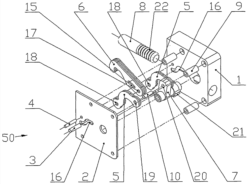
[0027] The content of this embodiment is mainly the buckle with the restraint chute.

[0028] figure 1 It is a schematic diagram of a lock hook assembly of a lock buckle and a rack latch provided by the present invention, figure 2 It is a schematic diagram of a detent assembly of a lock provided by the present invention. See figure 1 , the basic structure of the locking hook assembly 50. Hinged hole one 17 of lock hook 6 passes through lock hook shaft 3 and lock hook connecting rod 5 ( figure 1 The middle is made up of two parts side by side) the hinged hole two 18 at one end link to each other, the hinged hole three 19 of the other end of the locking hook connecting rod 5 links to each other with the connecting rod hinged hole four 20 on the inner hexagonal connecting rod shaft 7 by the connecting rod shaft 10, and the inner The two ends of the hexagonal connecting rod shaft 7 are installed on the lock hook cover plate 2 and the lock hook seat 1 respectively, and they fo...

Embodiment 2

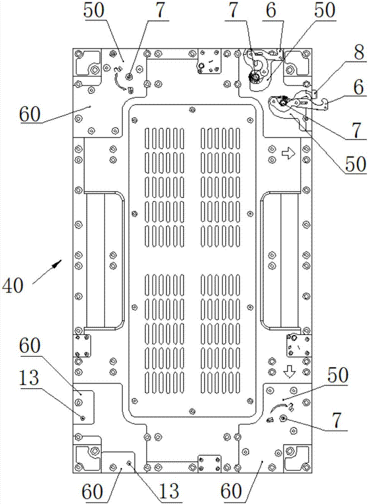
[0044] The content of this embodiment is mainly an LED box body equipped with a lock buckle with a constraint chute.

[0045] The lock with restraint chute can be used for splicing and installing cabinets, such as for splicing and installing LED cabinets. Figure 8 It is a schematic diagram of an LED box equipped with a lock buckle with a restraining chute provided by the present invention. see Figure 8 , The LED box body 40 includes an LED box shell, and the LED display assembly is installed on the LED box shell. On the two adjacent sides of the LED box shell, two lock hook assemblies 50 of the lock buckle with restraint chute of the present invention are respectively housed, a total of four, of which the upper right corner two have removed the lock hook cover plate, To show the lock hook 6 and the latch 8, one lock hook 6 is in a loose state, and the other is in a tightened state; position, respectively provided with two lock catch assemblies 60 of the present invention,...

Embodiment 3

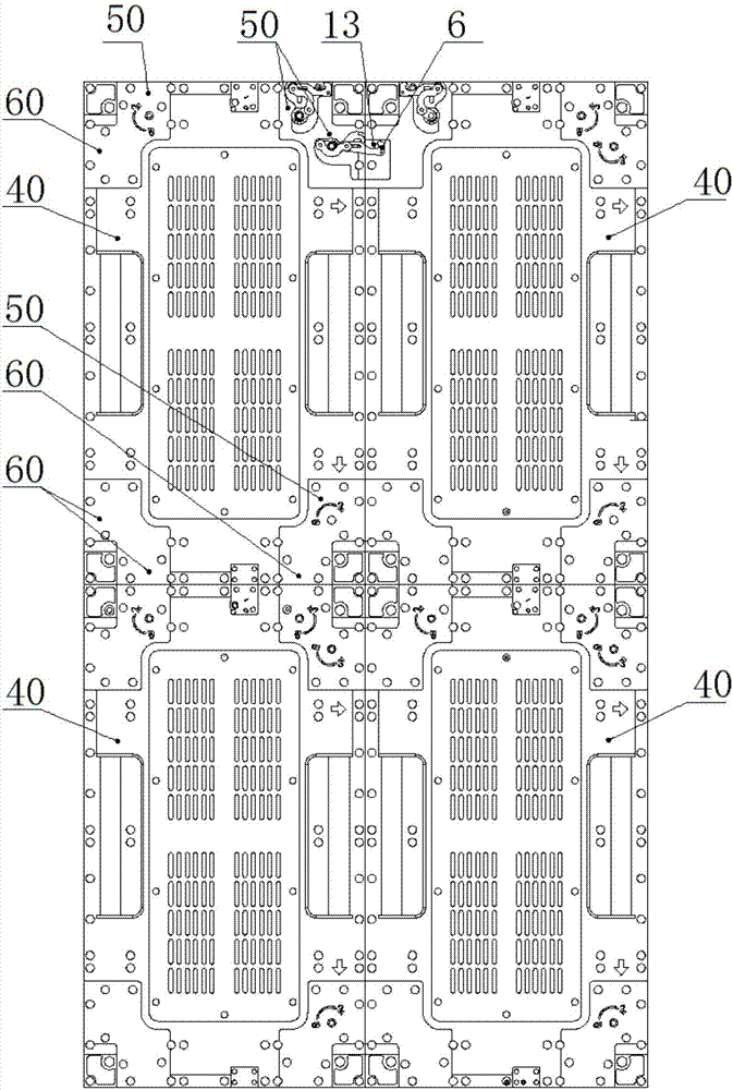
[0048] The content of this embodiment is mainly the LED display screen spliced ​​and installed using locks with restraint chutes.

[0049] Figure 9 It is a schematic diagram of an LED display screen connected by a lock provided by the present invention. see Figure 9 , a plurality of LED boxes 40 ( Figure 9 There are 4 pieces in the middle) are spliced ​​and installed with each other, and the adjacent LED boxes are connected to each other through their respective lock hook assemblies 50 and the other side's hook pin assemblies 60 to form an LED display screen. Wherein the screen upper end middle junction has unloaded the lock hook cover plate and the check pin cover plate, to show the lock hook 6 and the check pin 13 which are connected to each other. The lock provided by the present invention can bear the heavy weight of multiple LED cabinets 40, and the connection is firm, tight and precise. The LED box body can be connected and loosened by rotating the hexagonal conne...


PUM


Abstract

The invention provides a lock buckle with a restraining chute, which can be used for the tight splicing of the box body, including a lock hook assembly and a hook pin assembly. The lock hook of the four-bar linkage mechanism closely connects the lock hook assembly and the hook pin assembly, and is characterized in that: the lock hook shaft is fixed and the lock hook is provided with a lock hook chute; the lock hook cover and the lock hook seat are respectively provided with relative constraints The two ends of the chute and the locking hook shaft are respectively installed in the constraint chute and can move along the chute. The fixed shaft of the lock hook and the restraint chute make the movement of the atypical four-bar linkage mechanism adopted by the lock flexible and reliable, and it is not easy to get stuck; the lock hook has elastic stretching ability, which can eliminate the connection gap caused by processing errors; simple operation, one action The lock and latch can be completed, and it has self-locking ability. The LED display screen formed by connecting the LED cabinets with locks according to the present invention can bear a large weight of the LED cabinets, and the splicing is tight and precise. The LED screen cabinets can be connected and loosened with one action, and the operation is convenient.

Description

technical field [0001] The invention relates to machinery and structural devices, in particular to a lock with a restraining chute, an LED box and an LED display. Background technique [0002] Many devices composed of multiple cabinets need to solve the problem of close connection of the cabinets. For example, LED display screens are spliced ​​by LED cabinets equipped with LED display components, and various locks are often used for the connection of the cabinets. For example, the Chinese patent document CN102829039A "A Locking Connecting Device, LED Screen Cabinet and LED Display" discloses a lock. After pinning, press the handle to stretch the lock hook, so that the lock hook seat and the pin seat can be tightly connected, and at the same time, the handle makes the gear drive the latch to insert into the fixed pin hole on the pin seat. The disadvantage of the lock is that the handle affects the miniaturization of the lock, and the lock occupies the area of ​​the back cove...

Claims


Application Information

Patent Timeline
Patent Type & Authority Patents(China)
IPC IPC(8): H05K5/02G09F9/33
Inventor 潘尚法
Owner 上海大晨显示技术有限公司
Why Eureka
Try Eureka