
An electric ball valve

An electric ball valve and ball-type technology, which is applied in the direction of valve devices, multi-way valves, engine components, etc., can solve the problems of difficult installation environment compatibility, large installation space, and large compensation force, and achieve good compensation adaptability and installation space. Compatibility, the effect of reducing power loss

Inactive Publication Date: 2016-05-25
HUAZHONG UNIV OF SCI & TECH +1
View PDF8 Cites 0 Cited by
  • Summary
  • Abstract
  • Description
  • Claims
  • Application Information

AI Technical Summary

Problems solved by technology

[0009] (1) Due to the use of multiple disc springs stacked together for temperature, pressure and wear compensation, the volume of each disc spring is relatively large, resulting in an excessively large installation volume;
[0010] (2) It adopts a square structure, and the inlet and outlet are not arranged on the same end face, which is not conducive to the integration of pipeline installation and requires a large installation space. It is difficult to install the circular pipeline commonly used in the chemical industry such as Shiliu. Very good compatibility;
[0011] (3) The force generated by the compression amount of multiple disc springs is compensated, and the compression amount is selected according to the sealing requirements under high pressure conditions, which will inevitably cause excessive compensation force at low pressure, increase the friction force, and require a larger drive Power, but also accelerated the wear of the ball valve

Method used


Image

  • An electric ball valve
  • An electric ball valve

Examples


Embodiment Construction

[0028] In order to make the object, technical solution and advantages of the present invention clearer, the present invention will be further described in detail below in conjunction with the accompanying drawings and embodiments. It should be understood that the specific embodiments described here are only used to explain the present invention, not to limit the present invention. In addition, the technical features involved in the various embodiments of the present invention described below can be combined with each other as long as they do not constitute a conflict with each other.

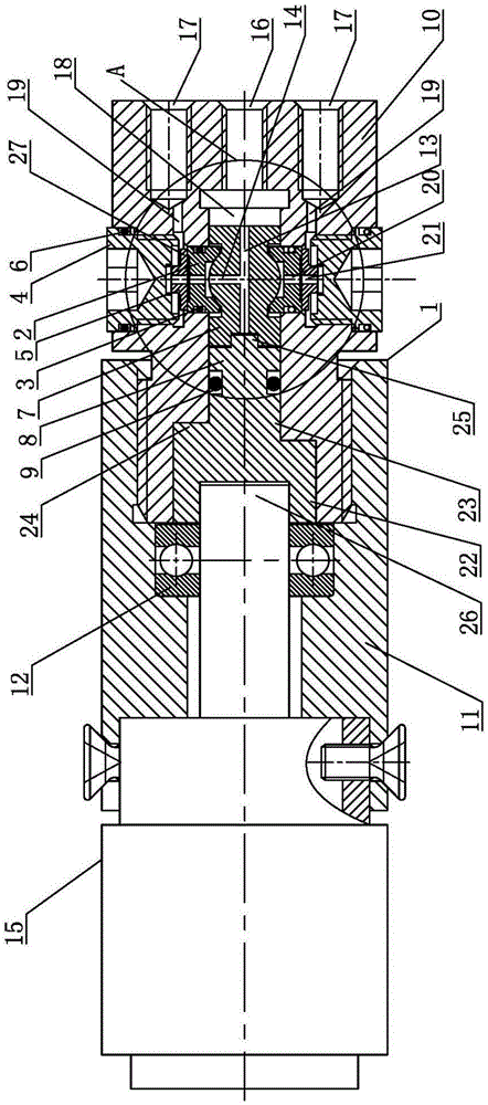
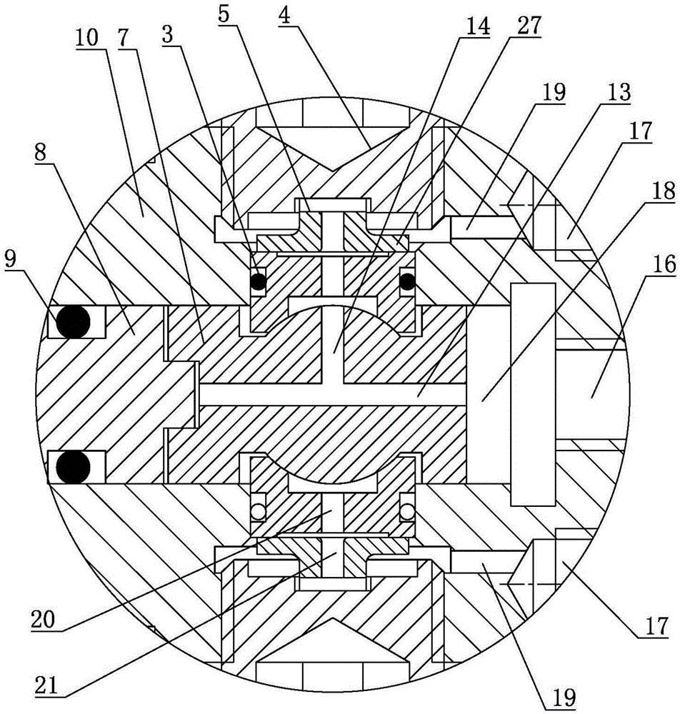
[0029] like Figure 1 ~ Figure 2 As shown, an electric ball valve includes a valve sleeve 1, a trunnion ball valve core 7 arranged in the valve sleeve 1, a valve seat 2 against the trunnion ball valve core 7, and a valve seat 2 capable of driving the trunnion ball valve core. The valve stem 8 that the valve core 7 rotates, the number of valve seats 2 is two, the two valve seats 2 are symmetrica...


PUM


Abstract

The invention discloses an electric ball valve, which comprises a valve housing, a trunnion ball type spool, valve seats and a valve rod, the valve housing comprises a valve body and a sleeve, the trunnion ball type spool is provided with an inflow passage and an outflow passage, a motor is mounted on the sleeve, the valve body is provided with an inflow hole and two outflow holes, the an inflow connecting passage and an outflow connecting passage are arranged in the valve body, a flexible compensating part which can elastically deform to apply elastic force to tightly press the valve seat abuts against each valve seat, a screw plug abuts against each flexible compensating part, the valve seats are provided with first central holes, and the flexible compensating parts are provided with second central holes. Since the flexible compensating parts are mounted to compensate the trunnion ball type spool and the valve seats and compensation is self-adaptive as temperature and pressure change, the electric ball valve has good self-adaptability in compensation, consequently, the electric ball valve can meet the different working condition requirements of geological strata at different depths, and the long-term safe and reliable sealing of the ball valve under different working conditions is ensured.

Description

technical field [0001] The invention belongs to the field of ball valves, and more specifically relates to an electric ball valve. Background technique [0002] In occasions such as nuclear power plants, crude oil extraction, and natural gas extraction, it is necessary to control high-temperature and high-pressure fluids. The water flooding fracturing technology often used in crude oil extraction is a water flooding multi-stage fracturing technology that uses plugging balls to perform staged fracturing on different layers. The casting diameter of the plugging balls decreases from top to bottom, and the corresponding pipeline The diameter is also reduced. For example, the ball valve is used in it, and the valve-controlled multi-stage fracturing technology is adopted. Compared with the traditional fracturing technology, the operation is simple, and only the corresponding control signal is given to control the positive and negative rotation of the motor to realize the reversin...

Claims


Application Information

Patent Timeline
Patent Type & Authority Patents(China)
IPC IPC(8): F16K5/06F16K5/08
CPCF16K5/0647F16K5/0657F16K5/08F16K11/0876
Inventor 刘银水韩明兴吴德发李东林赵旭峰邓亦攀李晓晖
Owner HUAZHONG UNIV OF SCI & TECH
Learn More