
Metallurgical bonding stainless steel cladding thermometal profile steel and preparing technology

A technology of metallurgical bonding and preparation process, applied in the field of metal composite materials and metallurgical steel rolling, can solve the problems of poor corrosion resistance and high cost, and achieve the effects of low price, beautiful appearance, excellent corrosion resistance and mechanical properties

Inactive Publication Date: 2017-06-13
丹阳恒庆复合材料科技有限公司
View PDF5 Cites 3 Cited by
  • Summary
  • Abstract
  • Description
  • Claims
  • Application Information

AI Technical Summary

Problems solved by technology

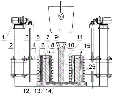
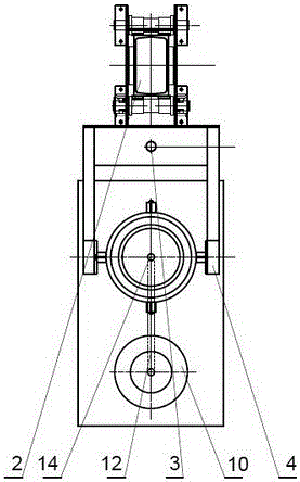
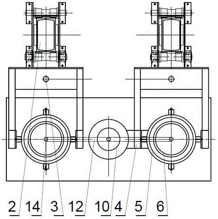
[0014] The purpose of the present invention is to overcome the deficiencies of the prior art, to solve the problem that stainless steel section steel has good corrosion resistance but high cost; carbon steel section steel has low cost but poor corrosion resistance, and provides a cost-effective and good corrosion resistance and A metallurgically combined stainless steel clad bimetal profile steel with oxidation performance and its preparation process can obtain good corrosion resistance and low cost, and can mass produce various bimetal clad steel products such as stainless steel clad angle steel, channel steel, H-beam, etc.

Method used


Image

  • Metallurgical bonding stainless steel cladding thermometal profile steel and preparing technology
  • Metallurgical bonding stainless steel cladding thermometal profile steel and preparing technology
  • Metallurgical bonding stainless steel cladding thermometal profile steel and preparing technology

Examples


Embodiment 1

[0076] Example 1: Preparation of metallurgically bonded stainless steel clad bimetallic angle steel.

[0077] Figure 17 Among them, the metallurgical combination of stainless steel clad bimetallic angle steel, its product specification is an equilateral bimetallic angle steel with a side length of 40mm and a thickness of 5nnn, which is composed of a carbon steel core metal 7 and a stainless steel cladding along the length direction of the core metal 7 Layer 6, between the stainless steel cladding 6 and the carbon steel core metal 7 is a metallurgically bonded fusion interface layer formed by melting and casting;

[0078] A metallurgically bonded stainless steel-clad bimetallic angle steel is prepared, the core 7 is carbon steel Q235A steel, the thickness of the stainless steel alloy layer 6 is 5 mm, and the stainless steel alloy layer 6 is selected from 06Cr19Ni10 austenitic stainless steel. Figure 17 It is a schematic structural diagram of a transverse cross-sectional view...

Embodiment 2

[0096] Example 2: Preparation of metallurgically bonded stainless steel clad bimetallic channel steel.

[0097] Figure 19 Among them, metallurgically combined stainless steel clad bimetallic channel steel, the product specification is 5# bimetallic channel steel, which is composed of carbon steel core metal 7 and stainless steel cladding 6 clad along the length direction of core metal 7, said Between the stainless steel cladding 6 and the carbon steel core metal 7 is a metallurgically bonded fusion interface layer formed by melting and casting;

[0098] The metallurgically bonded stainless steel clad bimetallic channel steel is prepared, and the core part 7 is the blank used for producing the HRB400 channel steel. The thickness of the stainless steel alloy layer 6 is 10 mm, and the stainless steel alloy layer 6 is made of 304 austenitic stainless steel. Figure 19 It is a schematic diagram of the basic structure of a bimetallic channel provided by the embodiment of the pres...

Embodiment 3

[0115] Example 3: Preparation of metallurgically bonded stainless steel-clad bimetallic H-shaped steel.

[0116] Figure 21 Among them, metallurgically combined stainless steel clad bimetallic channel steel, the product specification is 150×150×6 bimetallic H-shaped steel, which is composed of carbon steel core metal 7 and its stainless steel cladding 6 along the length direction of the core metal 7 , between the stainless steel cladding 6 and the carbon steel core metal 7 is a metallurgically bonded fusion interface layer formed by melting and casting;

[0117] The metallurgically bonded stainless steel clad bimetallic channel steel is prepared, and the core part 7 is the blank used for producing the HRB400 channel steel. The thickness of the stainless steel alloy layer 6 is 12 mm, and the stainless steel alloy layer 6 is made of 304 austenitic stainless steel. Figure 19 It is a schematic diagram of the basic structure of a bimetallic channel provided by the embodiment of ...


PUM

PropertyMeasurementUnit
Thicknessaaaaaaaaaa
Thicknessaaaaaaaaaa
Thicknessaaaaaaaaaa

Abstract

The invention discloses a metallurgically bonded stainless steel-coated bimetallic section steel and its preparation process, which includes a carbon steel core and a stainless steel cladding. Its composite forming process includes using an induction heater to integrally heat the outer stainless steel pipe to 600-1000°C. The inner layer of carbon steel is poured into molten metal and cast to produce a clad bimetal composite billet with a metallurgical bonding interface; the cast bimetal billet is hot-rolled into a clad bimetal steel section. The metallurgical bonding interface between the stainless steel layer and the carbon steel core is formed by melting and casting, and has the advantages of high bonding strength, excellent process performance, dense structure, good quality, few processes, low cost, and high efficiency. The present invention uses bimetallic section steel to replace the integral stainless steel section steel. On the premise of ensuring the corrosion resistance properties of the section steel, it not only saves stainless steel materials and reduces project costs, but also effectively improves the strength of steel bars, reduces waste of resources and energy and environmental pollution, and has Broad application prospects.

Description

Technical field [0001] The invention relates to the technical fields of metal composite materials and metallurgical steel rolling, and in particular to a metallurgical bonded stainless steel-coated bimetal steel bar and its preparation process. Background technique [0002] Section steel is a strip of steel with a certain cross-sectional shape and size. It is one of the four major varieties of steel (plate, tube, profile, and wire). According to the cross-section shape, section steel is divided into simple section section steel and complex section section steel (special-shaped steel). Simple section steel refers to square steel, round steel, flat steel, angle steel, hexagonal steel, etc.; complex section steel refers to I-beam, channel steel, rail, window frame steel, curved steel, etc. Section steel is generally used for machining, structural connection, etc. At present, angle steel, channel steel, I-beam, H-shaped steel, etc. are widely used in industry and construction....

Claims


Application Information

Patent Timeline
IPC IPC(8): B22D19/16B22D27/04
CPCB22D19/16B22D19/0081B22D27/045
Inventor 丁家伟丁刚耿德英鹿微微鹿策施孟达陈志和朱坚
Owner 丹阳恒庆复合材料科技有限公司
Learn More