Compensation type multipurpose annular blowout preventer

An annular blowout preventer, a multi-purpose technology, is applied in drilling equipment, wellbore/well components, earthwork drilling and production, etc. It can solve the problem of unadjustable self-sealing well sealing capacity, easy damage of the main rubber sleeve in the annular space, and the inner liner Holes are not round and other problems, to achieve the effect of light weight, low maintenance cost, and not easy to wear

Pending Publication Date: 2020-12-22
西安宇星石油机械新技术开发有限公司
View PDF0 Cites 4 Cited by
  • Summary
  • Abstract
  • Description
  • Claims
  • Application Information

AI Technical Summary

Problems solved by technology

[0004] The purpose of the present invention is to solve the problems of the existing blowout preventer, such as large volume, complicated replacement of rubber sleeves, high cost, low pressure resistance of self-sealing rubber sleeves, unadjustable self-sealing well capacity, easy damage of the main rubber sleeve in the annulus, and tightness in the circumferential direction. Behind the inner liner, the inner hole of the inner liner is not round, which causes the problem that the well pressure cannot be sealed, and a compensating multi-purpose annular blowout preventer is provided

Method used


Image

  • Compensation type multipurpose annular blowout preventer
  • Compensation type multipurpose annular blowout preventer
  • Compensation type multipurpose annular blowout preventer

Examples


Embodiment 1

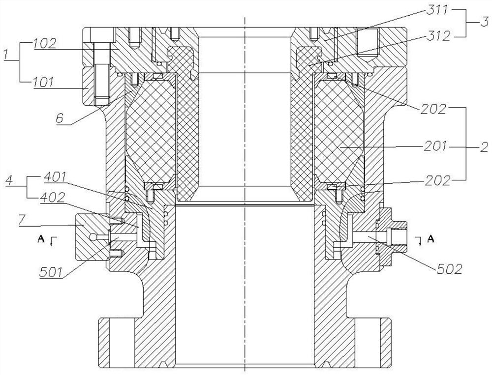
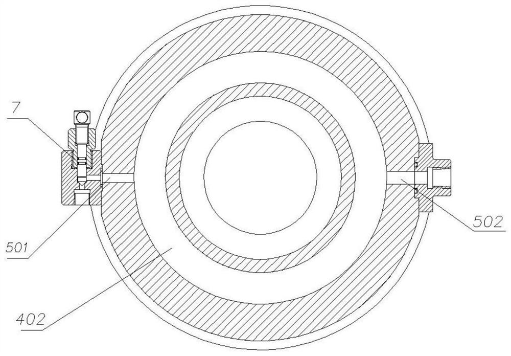
[0064] Such as figure 1 , figure 2 , image 3 As shown, the annular blowout preventer includes a shell 1, a main rubber sleeve assembly 2, and a secondary rubber sleeve assembly 3 arranged coaxially from the outside to the inside, which are located inside the shell 1 and arranged below the main rubber sleeve assembly 2 for The piston assembly 4 that squeezes the main rubber sleeve assembly 2 and the oil passage provided on the housing 1 and communicated with the piston assembly 4 .

[0065] In this embodiment, the housing 1 includes a housing body 101 and a flange 102 disposed on the upper end of the housing body 101 , and the housing 1 penetrates up and down inside.

[0066] The main rubber sleeve assembly 2 is set inside the shell body 101, including the main rubber sleeve 201 and two ring skeletons 202 respectively arranged on the upper end and the lower end of the main rubber sleeve 201, where the two ring skeletons 202 and the main rubber sleeve 201 are integrated str...

Embodiment 2

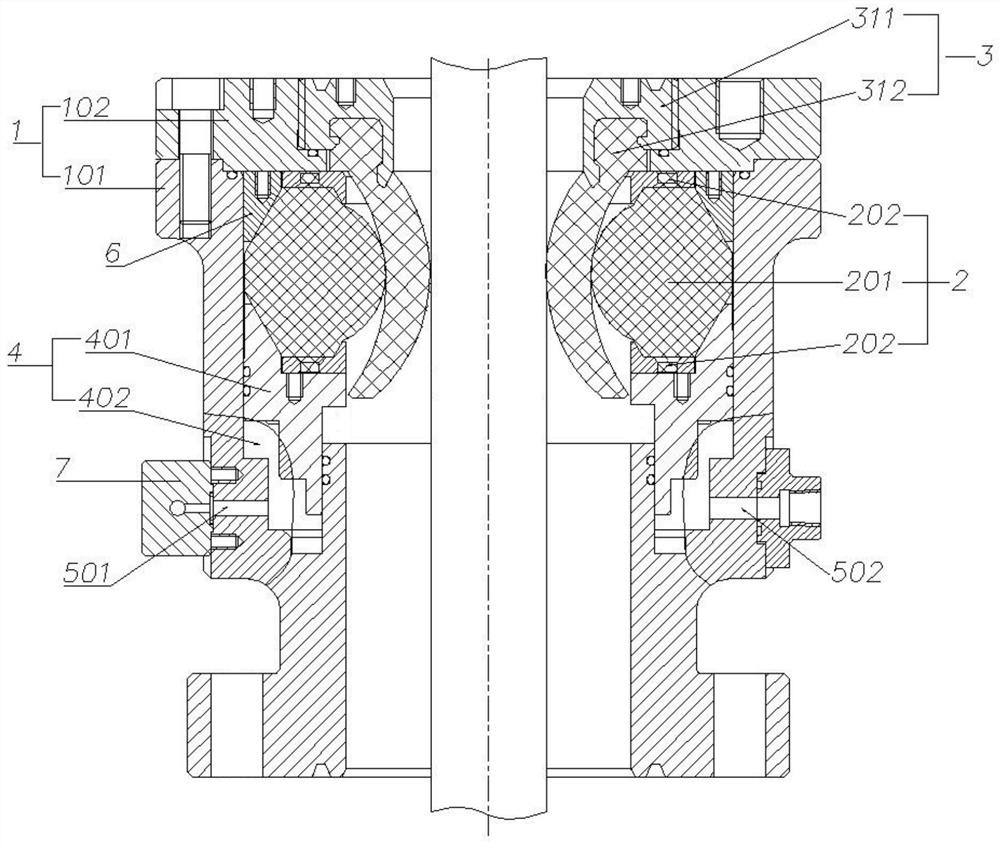
[0077] Such as Figure 4 As shown, the annular blowout preventer includes a shell 1, a main rubber sleeve assembly 2, and a secondary rubber sleeve assembly 3 arranged coaxially from the outside to the inside, which are located inside the shell 1 and arranged below the main rubber sleeve assembly 2 for The piston assembly 4 that squeezes the main rubber sleeve assembly 2 and the oil passage provided on the housing 1 and communicated with the piston assembly 4 .

[0078] In this embodiment, the housing 1 includes a housing body 101 and a flange 102 disposed on the upper end of the housing body 101 , and the housing 1 penetrates up and down inside.

[0079] The main rubber sleeve assembly 2 is set inside the shell body 101, including the main rubber sleeve 201 and two ring skeletons 202 respectively arranged on the upper end and the lower end of the main rubber sleeve 201, where the two ring skeletons 202 and the main rubber sleeve 201 are integrated structure. The inside of t...

Embodiment 3

[0086] Such as Figure 5 As shown, the annular blowout preventer includes a shell 1, a main rubber sleeve assembly 2, and a secondary rubber sleeve assembly 3 arranged coaxially from the outside to the inside, which are located inside the shell 1 and arranged below the main rubber sleeve assembly 2 for The piston assembly 4 that squeezes the main rubber sleeve assembly 2 and the oil passage provided on the housing 1 and communicated with the piston assembly 4 .

[0087] In this embodiment, the housing 1 includes a housing body 101 and a flange 102 disposed on the upper end of the housing body 101 , and the housing 1 penetrates up and down inside.

[0088] The main rubber sleeve assembly 2 is set inside the shell body 101, including the main rubber sleeve 201 and two annular skeletons 202 respectively arranged on the upper end and the lower end of the main rubber sleeve 201, where the two annular skeletons 202 and the main rubber sleeve 201 are integrated structure. The insid...


PUM


Abstract

The invention relates to an oil well blowout preventer, in particular to a compensation type multipurpose annular blowout preventer so as to solve the problems that an existing blowout preventer is large in size, complex in rubber sleeve replacement and high in cost, a self-sealing rubber sleeve is low in pressure resistance, the self-sealing well sealing capacity cannot be adjusted, an annular main rubber sleeve is prone to being damaged, and after an inner bush is annularly held, an inner hole of the inner bush is not round, and consequently the well pressure cannot be sealed. The annular blowout preventer comprises a shell, a main rubber sleeve assembly, an auxiliary rubber sleeve assembly, a piston assembly and an oil way, all of which are coaxially arranged in sequence from outside toinside, the piston assembly is located on the inner side of the shell, arranged below the main rubber sleeve assembly and used for extruding the main rubber sleeve assembly, and the oil way is arranged on the shell and communicates with the piston assembly. The auxiliary rubber sleeve assembly comprises an auxiliary rubber sleeve and an auxiliary rubber sleeve framework, the auxiliary rubber sleeve is arranged on the inner side of the main rubber sleeve assembly, the upper end of the auxiliary rubber sleeve is fixedly connected with the auxiliary rubber sleeve framework, the auxiliary rubbersleeve framework is detachably connected with the upper end of the shell, and the auxiliary rubber sleeve assembly is used for tightly holding an oil pipe, a workover tool, a cable, a steel wire ropeor a sucker rod under extrusion of the main rubber sleeve assembly.

Description

technical field [0001] The invention relates to the field of blowout preventers, in particular to a compensation type multipurpose annular blowout preventer. Background technique [0002] At present, in oilfield workover and testing operations, the wellhead must be equipped with blowout preventers, the purpose of which is: 1. To meet the requirements for blowout prevention and sealing of the annulus at the wellhead for tubing, couplings, and tool strings of different diameters; 2. Prevent the oil and water gas from the tubing and casing annulus from upwelling and ejecting from the wellhead annulus; 3. Scrape off the oil on the outer wall of the tubing to reduce the workload of cleaning the tubing on the ground; 4. Prevent the wellhead from falling into the well; 5. Righting the tubing. [0003] In the prior art, conventional annular blowout preventers, portable self-sealing sealers, hydraulic control sealers or compensating annular blowout preventers are generally installed...

Claims


Application Information

Patent Timeline
Patent Type & Authority Applications(China)
IPC IPC(8): E21B33/06E21B17/10
CPCE21B17/1035E21B17/1071E21B33/06
Inventor 郭瑞安姚谋安杰马新东齐加德娄真真聂斌邢建峰雷宽成
Owner 西安宇星石油机械新技术开发有限公司
Why Eureka
Try Eureka