Polarizing plate, optical film and image display device

A technology of polarizing plate and cellulose ester film, which is applied in the direction of optics, optical elements, polarizing elements, etc., can solve the problem of panel display unevenness, and achieve the effects of small display unevenness, suppression of phase difference change, and excellent durability

Active Publication Date: 2018-02-09
NITTO DENKO CORP
View PDF20 Cites 0 Cited by
  • Summary
  • Abstract
  • Description
  • Claims
  • Application Information

AI Technical Summary

Problems solved by technology

However, the retardation of the cellulose ester film generally used as a transparent protective film changes greatly in a high-humidity environment, and there is a problem that display unevenness occurs on the panel.

Method used


Image

  • Polarizing plate, optical film and image display device

Examples


Embodiment

[0110] Hereinafter, examples of the present invention will be described, but the embodiments of the present invention are not limited thereto.

[0111]

[0112] A polyvinyl alcohol film having an average degree of polymerization of 2400 and a degree of saponification of 99.9 mol % and a thickness of 75 μm was immersed in warm water at 30° C. for 60 seconds to swell. Next, the film was dyed while being immersed in an aqueous solution having a concentration of 0.3% of iodine / potassium iodide (weight ratio = 0.5 / 8), and stretched to 3.5 times. Then, stretching was carried out so that the total stretching ratio became 6 times in a borate aqueous solution at 65°C. After stretching, it was dried in a 40° C. oven for 3 minutes to obtain a PVA-based polarizing plate (thickness: 23 μm).

[0113]

reference example 1

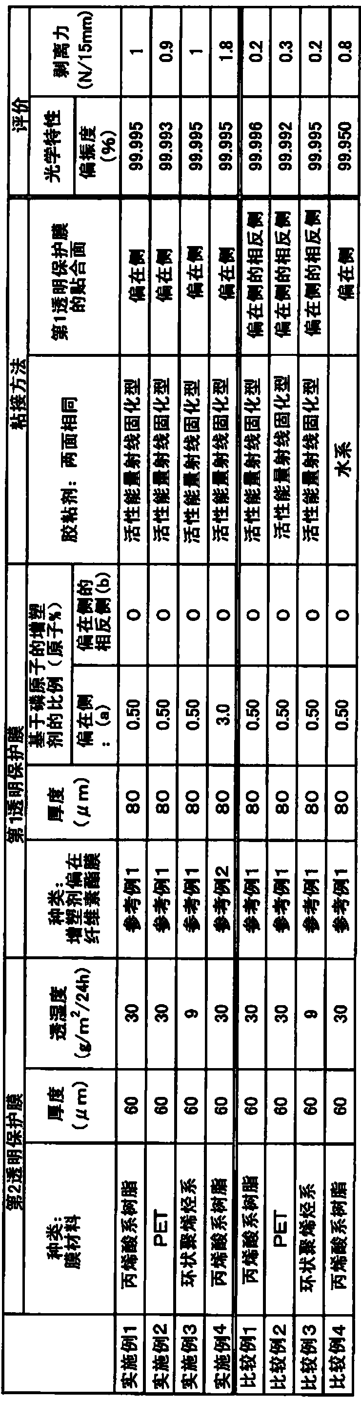
[0115] A plasticizer-localized cellulose ester film with a thickness of 80 μm was obtained. The ratio (a) of the phosphorus-based plasticizer based on phosphorus atoms on the side of the film is 0.5 atomic %; the ratio (b) of the phosphorus-based plasticizer on the opposite side of the film is 0 atom%.

[0116] The cellulose ester film in which the above-mentioned plasticizer is partial is produced by the following method.

[0117] 100 parts by weight of cellulose triacetate (the degree of acetyl substitution is 2.88, and the number average molecular weight is 150,000),

[0118] 10 parts by weight of triphenyl phosphate (phosphorus plasticizer),

[0119] 2 parts by weight of ethyl phthalate ethyl glycolate

[0120] チヌビン 326 (manufactured by Ciba Specialty Chemicals Co., Ltd.) 1 part by weight

[0121] AEROSIL 200V (manufactured by Aerosil Japan) 0.1 parts by weight

[0122] Acicular TiO 2 (manufactured by Ishihara Sangyo Co., Ltd., trade name FTL-100) 5 parts by weight ...

reference example 2

[0131] A plasticizer-localized cellulose ester film having a thickness of 80 μm was obtained. The ratio (a) of the phosphorus-based plasticizer based on phosphorus atoms on the side of the film is 3 atomic %; the ratio (b) of the phosphorus-based plasticizer on the opposite side of the film is 0 atom%. In the reference example 1, except having changed the compounding ratio of the triphenyl phosphate to 60 weight part, it carried out similarly to the reference example 1, and prepared this film.

[0132] Determination of the proportion of plasticizer

[0133] The proportions (a: atomic %) and (b: atomic %) of the plasticizer in the cellulose ester film were measured based on the phosphorus atoms in the plasticizer by ESCA. It should be noted that the measurement of the above-mentioned ratio (a) is carried out on the range from the side where the plasticizer is biased to a thickness of 5 nm (the biased side), and the measurement of the above-mentioned ratio (b) is from the oppo...


PUM

PropertyMeasurementUnit
thicknessaaaaaaaaaa
thicknessaaaaaaaaaa
thicknessaaaaaaaaaa

Abstract

In the polarizing plate of the present invention, the first and second transparent protective films are bonded to both sides of the polarizer through an adhesive layer formed by irradiating an active energy ray-curable adhesive with active energy rays, wherein at least the second 1. The transparent protective film is made of plasticizer and cellulose ester, and the plasticizer is partial to the cellulose ester film, and the plasticizer is partial to the cellulose ester film, and the plasticizer is partial to the cellulose ester film. The face side of the agent is bonded by the adhesive layer. This polarizing plate can satisfy optical characteristics and adhesive force even when a cellulose ester film is used as a transparent protective film.

Description

technical field [0001] The present invention relates to a polarizing plate in which a transparent protective film is provided on both surfaces of a polarizing plate through an adhesive formed of an active energy ray-curable adhesive. This polarizing plate can form image display devices, such as a liquid crystal display device (LCD), organic electroluminescent display device, CRT, PDP, etc., individually or in the form of the optical film which laminated|stacked it. Background technique [0002] A liquid crystal display device visualizes a polarization state by switching liquid crystals. According to the display principle, a polarizing plate is used in which a transparent protective film is bonded to both sides of a polarizing plate via an adhesive layer. As a polarizing plate, since it is required to have a high transmittance and a high degree of polarization, for example, an iodine-based polarizing plate having a structure in which iodine is adsorbed to polyvinyl alcohol an...

Claims


Application Information

Patent Timeline
Patent Type & Authority Patents(China)
IPC IPC(8): G02B5/30B32B7/02B32B23/20G02F1/1335G02F1/13363B32B7/023
CPCB32B23/20G02B5/3033B32B7/12B32B23/04B32B2307/412B32B2307/42B32B2457/20G02B1/14B32B7/023
Inventor 村山俊介中田美惠竹田哲郎山下智弘
Owner NITTO DENKO CORP
Why Eureka
Try Eureka