
Mould used for making pre-deformed blister tray structure

A pre-deformation and mold technology, which is applied in the field of molds for making pre-deformation plastic tray structures, can solve the problems of inconvenient users of the tray structure and the inability to effectively guarantee the quality, so as to improve quality and production efficiency, with simple structure and low cost. low effect

Pending Publication Date: 2018-07-27
NINGBO XIYUE ZHIXING TECH CO LTD
View PDF0 Cites 0 Cited by
  • Summary
  • Abstract
  • Description
  • Claims
  • Application Information

AI Technical Summary

Problems solved by technology

[0004] The technical problem to be solved by the present invention is to provide a mold for making a pre-deformed blister tray structure, so as to overcome the deformation of the tray structure formed in the prior art, which is concave in the reverse direction, so that the quality cannot be effectively guaranteed , the defect that brings inconvenience to the users of the pallet structure

Method used


Image

  • Mould used for making pre-deformed blister tray structure
  • Mould used for making pre-deformed blister tray structure
  • Mould used for making pre-deformed blister tray structure

Examples


Embodiment 1

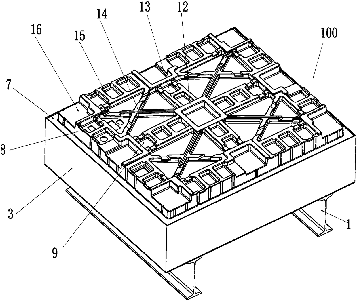
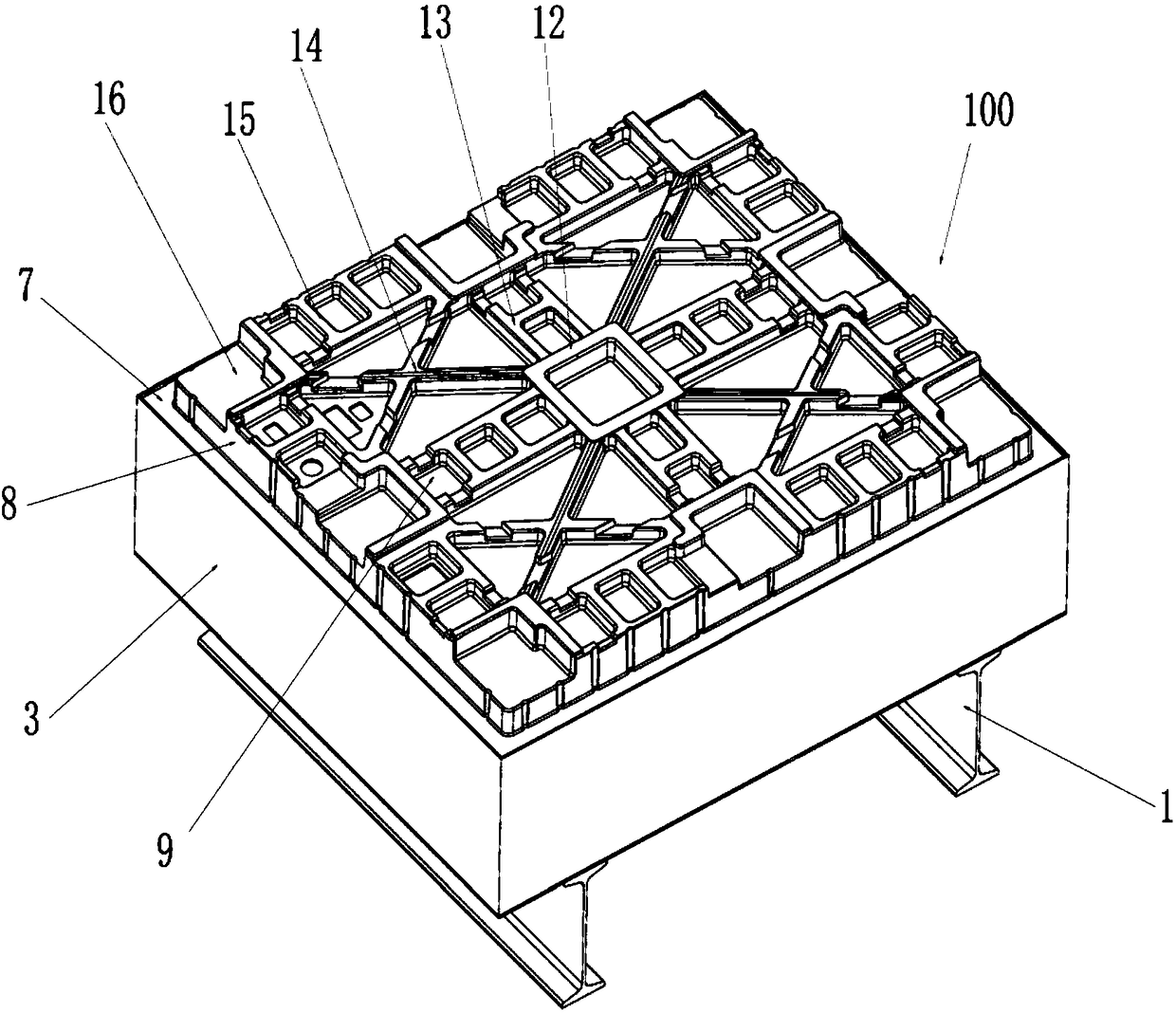
[0018] Such as figure 1 , 2 , 3, and 4, the mold 100 used to make the pre-deformed plastic tray structure of the present embodiment includes a support frame 1, a mold core 2, a mold body 3, and a water inlet pipe arranged on the mold body 4. Outlet pipe 5, vacuum chamber, vacuum connecting pipe 6; the water inlet pipe and the water outlet pipe communicate with the external water source through the water pump, the support frame supports the mold body, and the mold core is arranged on the upper end of the mold body, A cooling water pipe is laid in the mold body, and the cooling water pipe is connected to the water inlet pipe and the water outlet pipe for water circulation cooling. Shaped core body 8, the core frame seat 7 is flush with the upper end of the mold body 3. The middle part of the mold core body is in a raised state, and then continuously extends from the middle part to the surroundings and lowers. There are a number of air extraction holes 9 evenly distributed on t...

Embodiment 2

[0022] Such as image 3 , 4 As shown, the second embodiment is basically the same as the first embodiment, except that the mold core 2 in this embodiment is made of thermosetting phenolic resin material. Described phenolic resin is that solid phenolic resin is yellow, transparent, amorphous mass, because it contains free phenol, it is reddish, and the specific gravity of the entity is about 1.7 on average, soluble in alcohol, insoluble in water, to water, weak acid, Weak base solution is stable. It is a resin made by polycondensation of phenol and formaldehyde under catalyst conditions, neutralization and washing with water. Due to the choice of catalyst, it can be divided into two types: thermosetting and thermoplastic. Phenolic resin has good acid resistance, mechanical properties and heat resistance, and is widely used in anti-corrosion engineering, adhesives, flame retardant materials, grinding wheel manufacturing and other industries. Since the mold core is made of ph...


PUM


Abstract

The invention discloses a mould used for making a pre-deformed blister tray structure. The mould comprises a supporting frame. The supporting frame supports a mould body. A mould core is arranged at the upper end of the mould body. A cooling water pipe is laid in the mould body and communicates with a water inlet pipe and a water outlet pipe to conduct water circulating cooling. A vacuum connecting pipe is connected with a vacuum air pump. The mould core comprises a mould core frame seat and a mould core body with the tray shape. The middle of the mould core body is in a raised state, and themould core body continuously extends to decline from the middle to the periphery. A plurality of air pumping holes are evenly distributed in the mould core body. The air pumping holes communicate witha vacuum chamber. The vacuum chamber communicates with the vacuum connecting pipe. The mould used for making the pre-deformed blister tray structure is simple in structure and low in cost; the middleof a made tray structure product is in the raised state towards the obverse side, namely, the tray structure product first takes pre-deformation measures, the tray structure product can automaticallyrestore to a flat state after stress shrinkage of the tray structure product, the quality of the tray structure product is ensured, and the requirement of a user is met.

Description

technical field [0001] The invention relates to the field of molds, in particular to a mold for making a pre-deformed blister tray structure. Background technique [0002] Blister molding machine is a device used for plastic molding of plastic products, which includes a frame, a sheet material supply device, a heating device, a mold tank, a vacuum system and a sheet material conveying chain, and the mold is set in the mold tank. The principle of blister molding is: a plastic sheet is baked and softened by a heating device, and the softened sheet needs to be sent to the mold groove through a conveying chain, and then the vacuum pump generates negative pressure to absorb the plastic sheet to the surface of the mold. Forming, cooling and shaping into tray structures of different shapes. [0003] However, in the current plastic forming technology, the molded tray structure is prone to deformation due to stress shrinkage, that is, the tray structure product is concave in the rev...

Claims


Application Information

Patent Timeline
IPC IPC(8): B29C51/36B29C51/42
CPCB29C51/36B29C51/428
Inventor 黄益祥罗胤豪
Owner NINGBO XIYUE ZHIXING TECH CO LTD
Learn More