Following rotation preventing rotary blade reverse type mini-tiller

A micro-tiller and reverse-type technology, which is applied in the field of micro-tillers, can solve problems such as failure to achieve results, lower production efficiency, and reduced safety of finished micro-tillers.

Inactive Publication Date: 2015-09-16
GAOYOU NORTH POWER MACHINERY
View PDF7 Cites 0 Cited by
  • Summary
  • Abstract
  • Description
  • Claims
  • Application Information

AI Technical Summary

Problems solved by technology

At present, in similar micro tillage machines, flat belts without internal cogs are used. After the clutch switch is released, there is often a certain friction between the belt and the driving wheel, which often causes the belt to rotate, causing the The cultivating knife cannot stop rotating within 5 seconds. In order to prevent this kind of bad phenomenon, it is necessary to carry out multiple debugging on the production line during production, but sometimes the effect cannot be achieved after debugging, which greatly wastes the operating time of the debugging station and reduces production efficiency. , so that the use safety of the finished micro tillage machine is reduced
[0003] On the other hand, in terms of transmission mode, most micro tillage machines use single worm gear transmission, that is, a worm and a worm gear are connected to each other for transmission. Being dragged forward to rotate, the rotation direction of the wheel and the tiller blade are both in the same direction and moving forward. In this case, the stay time of the tiller blade on the same plowing field is too short, resulting in a poor effect after one-time plowing. , it often needs to go back and forth to cultivate the land many times, which reduces the efficiency of the cultivated land

Method used


Image

  • Following rotation preventing rotary blade reverse type mini-tiller
  • Following rotation preventing rotary blade reverse type mini-tiller
  • Following rotation preventing rotary blade reverse type mini-tiller

Examples


Embodiment 1

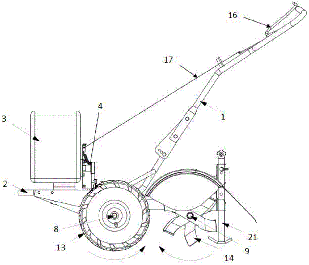
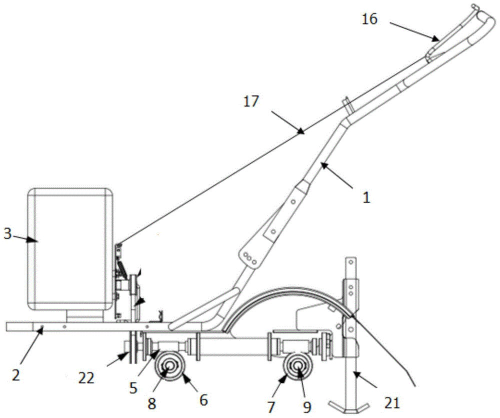
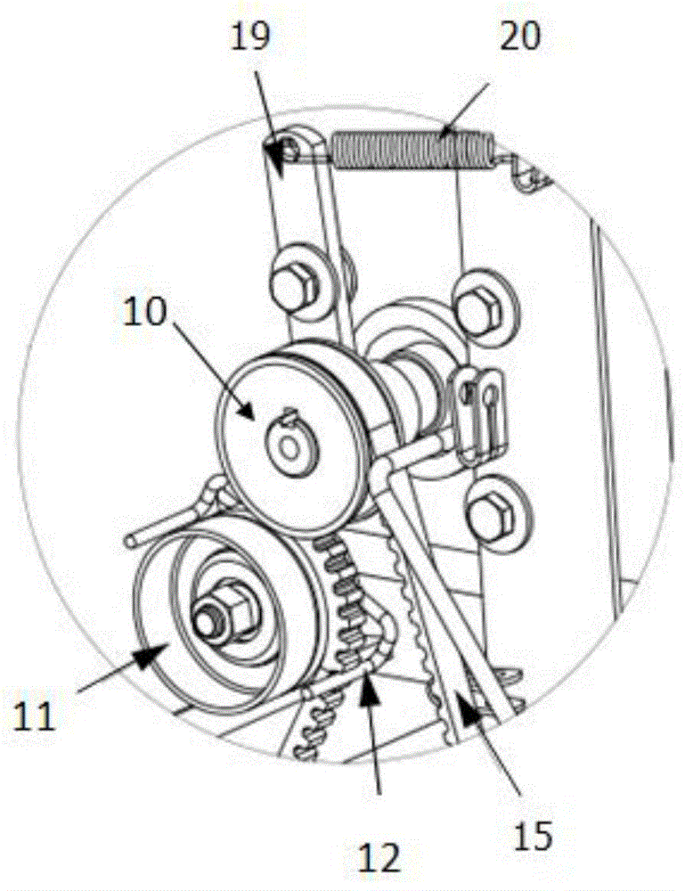
[0022] Such as Figure 1-Figure 4 In the anti-heel-rotating cultivating knife reverse micro tillage machine shown, the handrail 1 is connected to the frame 2, and the power 3 is connected to the frame 2. The power 3 is connected to the wheel 13 and the tiller 14 through the transmission mechanism 4, and is located on the handrail 1. The clutch switch 16 is connected to the transmission mechanism 4 through the connection line 17. The transmission mechanism 4 includes an inner toothed belt 15 which is sleeved and connected between the driving wheel 10 and the tension pulley 18. The inner tooth surface of the inner toothed belt 15 is connected to the The driving wheel 10 fits loosely, the non-internal tooth surface of the belt with internal cogging 15 fits loosely with the tensioning wheel 18, the thickness of the belt 15 with internal cogging is 0.1 cm, the depth of the internal teeth is 0.5 cm, and the belt stopper 12 Connected with the tensioning wheel 18, the distance between...

Embodiment 2

[0024] When utilizing a kind of anti-following tiller described in embodiment 1 to work, start the power 3, and when pressing the clutch switch 16, the connecting wire 17 will lift the tension arm 19, causing the tension spring 20 Tensile deformation is generated, and the tension arm 19 drives the tension wheel 18 to press the inner cogged belt 15, so that the inner cogged belt 15 and the driving wheel 10 are closely attached, and at the same time, the belt stopper 12 and the inner cogged belt The internal cogging of 15 is separated. At this time, the friction between the internal cogged belt 15 and the driving wheel 10 drives the driving wheel 10 to rotate, and the driving wheel 10 drives the driven wheel 22 to rotate through the internal cogging belt 15, thereby driving the worm 5 rotates, and now the wheel worm gear 6 and the cultivating blade worm gear 7 that are connected to the worm 5 rotate respectively, and the rotation direction of the wheel worm gear 6 and the cultiva...

Embodiment 3

[0027] Such as Figure 1-Figure 4 In the anti-heel-rotating cultivating knife reverse micro tillage machine shown, the handrail 1 is connected to the frame 2, and the power 3 is connected to the frame 2. The power 3 is connected to the wheel 13 and the tiller 14 through the transmission mechanism 4, and is located on the handrail 1. The clutch switch 16 is connected to the transmission mechanism 4 through the connection line 17. The transmission mechanism 4 includes an inner toothed belt 15 which is sleeved and connected between the driving wheel 10 and the tension pulley 18. The inner tooth surface of the inner toothed belt 15 is connected to the The driving wheel 10 fits loosely, and the non-internal tooth surface of the belt inner toothed belt 15 fits loosely with the tensioning wheel 18. The thickness of the belt inner toothed belt 15 is 1 cm, and the depth of the inner teeth is 1 cm. The tension wheel 18 is connected, and the distance between the belt retaining member 12 ...


PUM


Abstract

The invention provides a following rotation preventing rotary blade reverse type mini-tiller and belongs to the field of agricultural machines. According to the following rotation preventing rotary blade reverse type mini-tiller, a conveying mechanism comprises a belt with an internal tooth groove, a worm, a wheel worm wheel and a rotary blade worm wheel, the belt with the internal tooth groove is connected between a driving wheel and a tensioning wheel in a sleeving mode, a belt stop part is connected with the tensioning wheel and clamped with the internal tooth groove of the belt of the internal tooth groove, the wheel worm wheel and the rotary blade worm wheel are connected to the front and the rear of the worm respectively, the rotating directions of the wheel worm wheel and the rotary blade worm wheel are opposite, a wheel axle and a rotary blade shaft are connected to the center of the wheel worm wheel and the center of the rotary blade worm wheel respectively, and the wheel axle and the rotary blade shaft are connected with wheels and rotary blades respectively. The function of the mini-tiller is practical, the belt with the internal tooth groove is improved and then utilized, the belt stop part is used cooperatively, the belt can not rotate in a following mode again after stopping rotating fast, and therefore the use safety of the mini-tiller is improved; a transmission mode is modified into transmission of the worm and the double worm wheels, soil after being plowed one time is more thorough and finer compared with that plowed by a traditional mini-tiller, and the plowing efficiency and the practicality of the mini-tiller are greatly improved.

Description

technical field [0001] The invention belongs to the field of agricultural machinery, in particular to a tiller. Background technique [0002] As a commonly used agricultural machine, the tiller is more and more widely used in China's agricultural production, and plays an increasingly important role in plowing and farming. On the one hand, in the standard requirements, when the tiller is stopped, the tiller must stop rotating within 5 seconds, otherwise the safety of the tiller will be reduced. At present, in similar micro tillage machines, flat belts without internal cogs are used. After the clutch switch is released, there is often a certain friction between the belt and the driving wheel, which often causes the belt to rotate, causing the The cultivating knife cannot stop rotating within 5 seconds. In order to prevent this kind of bad phenomenon, it is necessary to perform multiple debugging on the production line during production, but sometimes the effect cannot be achi...

Claims


Application Information

Patent Timeline
Patent Type & Authority Applications(China)
IPC IPC(8): A01B33/02A01B33/08
Inventor 柏远康常胜安张正
Owner GAOYOU NORTH POWER MACHINERY
Why Eureka
Try Eureka